Triple Screen Flight Sim at the National Airline History Museum

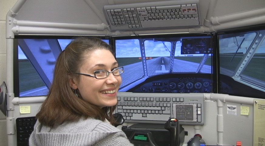
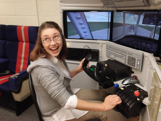
I built a flight simulator and donated it to a local aviation museum. The museum guests enjoy a hands-on experience because they get to fly the simulator. Some people say the Triple Screen Flight Sim at the National Airline History Museum is their favorite part of the museum.

National Airline History Museum

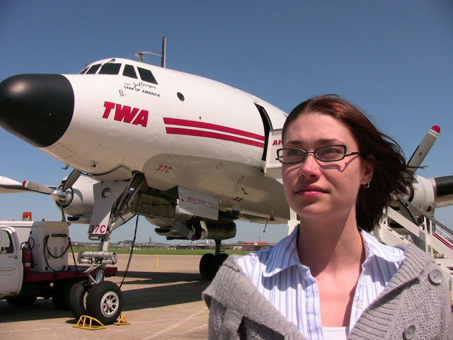
The NAHM is the only airline-specific museum in the United States. The museum has several airliners but the Lockheed Constellation is the crown jewel of the collection. The Triple Screen Flight Sim allows visitors to fly a simulated Constellation just like the one in the museum.

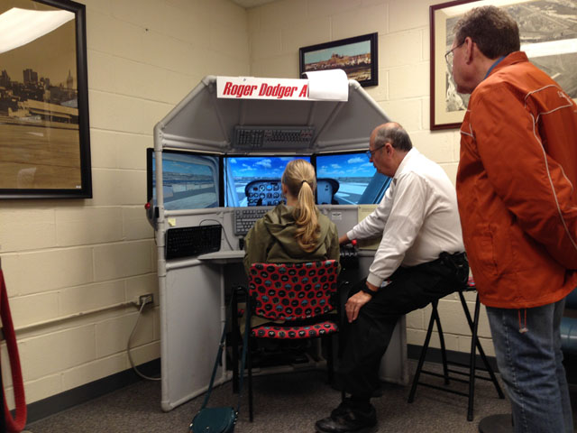
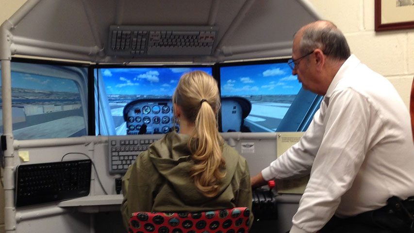
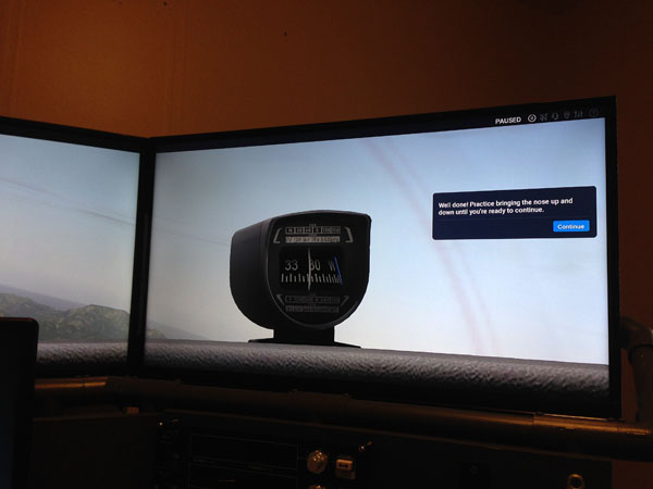
The Triple Screen Flight Sim at the National Airline History Museum is also used as a introduction to general aviation. Visitors receive a flight “lesson” as they fly a simulated Cessna 172. A museum volunteer personally teaches some basic flight maneuvers while the guest tries them in the sim. The simulator is such an excellent teaching tool because you can pause the flight to answer questions or explain something in more detail.


Triple Screen Flight Sim

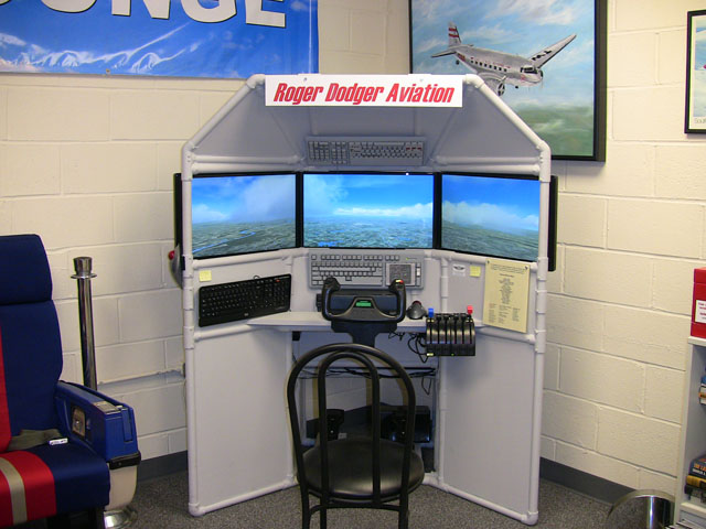
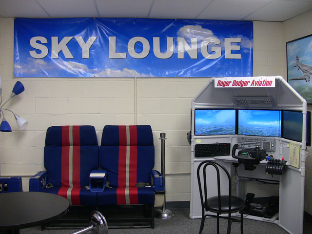
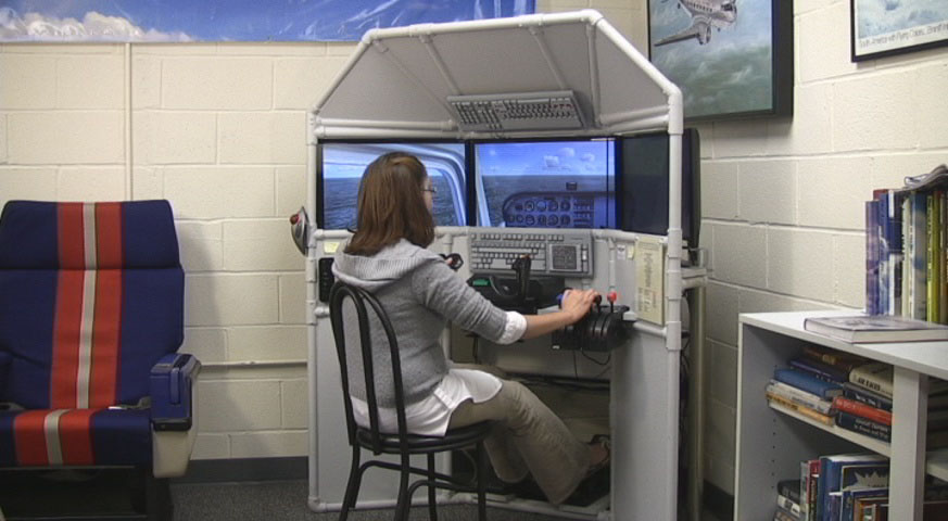
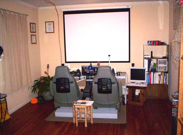
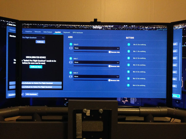
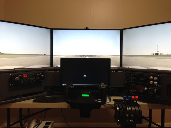
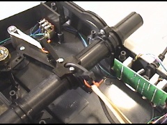
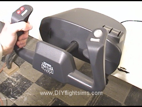
The pictures here show a stock version of the DIY Triple Screen Flight Sim at the National Airline History Museum. My DIY video and instruction manual show you how to build this same project from PVC pipes, lumber, and foam insulation. I installed a Saitek Pro Flight yoke, throttle and rudder pedals in this particular project. The painted keyboards are stock versions of the DIY Keyboard Mod: Airliner project.

The DIY Triple Screen Flight Sim is the perfect addition to the Sky Lounge at the NAHM, and it would be a perfect addition to your home.

Kickstarter Fund-Raiser

This project was the first successful flight simulator project ever funded through Kickstarter. It is truly historical. The fund raising campaign paid for the supplies and materials I needed to build the project from scratch. After I built it, I brought it to the Kansas City Maker Faire and then to the NAHM.


The Triple Screen Flight Sim at the National Airline History Museum

Tacky, Old, Roger Dodger Aviation Headquarters

Long before I started making the DIY Flight Sims videos, I provided aviation training and simulator rental out of my home. This wasn’t as odd as it may seem at first. I remember as a kid, my mom would go to a stylist that had a salon built into her house. A lot of people run small businesses from their home and so I started an aviation training center in my living room. We did a lot of good training at the Roger Dodger Aviation Headquarters from 2005 to 2009.

Roger Dodger Aviation Headquarters

I had one flight simulator, the Roger Dodger Aviation Training System (RDATS). I used this simulator to teach people about flying that was very similar to the approach I used when I instructed in actual airplanes. We started each lesson by briefing at the table, and then moved to the simulator to perform an abbreviated preflight. Next, we flew the lesson and performed the maneuvers from the FAA Practical Test Standards booklet. I demonstrated each maneuver while describing it, and then the student attempted the same maneuver while I verbally coached them. The Roger Dodger Aviation Headquarters had actual training videos for students to view. I always had a selection of free sodas available for students.


TrackIR For a Dual Seat Flight Sim

The TrackIR view tracking system was a revolutionary technology at the time. Furthermore, I wouldn’t have had any interest in flight simulators without it. TrackIR allows you to look around the virtual cockpit by simply moving your head. It is an infrared camera that sees reflectors on your cap. TrackIR was vitally important to my lessons because the students needed the ability to look around their virtual environment. In real airplanes, we are always looking around, scanning for traffic, and maintaining situational awareness so this had to be included in the simulation too.

TrackIR was designed to detect one pilot only, so how did I adapt it for two? I attached the TrackIR camera on a sliding pedestal. We would simply move the pedestal in front of whichever pilot was flying at that moment. As a result, this was just a part of the positive exchange of controls that is an important part of instruction. In other words, we always verbally designate which pilot is flying.

I built a base to include two seats from a Dodge Caravan. These seats were wonderfully comfortable, fully adjustable, and very sturdy. You can see more about those seats in this video.

South Pacific Theme

I decorated the Roger Dodger Aviation Headquarters in tacky island-theme party decorations. I wanted it to feel like you had traveled to someplace different than Kansas. Look at the walls, they are covered with a thatch-weave paper, as well as fish nets, plastic sea creatures, airplane pictures, and more. The island theme also worked well with the addition of the Air Combat Training Simulators (ACTS) that I was also developing. We later flew the ACTS sims in a lot of South Pacific WW2 missions.

I’m a real Certified Flight Instructor but we didn’t log this as credit towards any actual license. I found that people were naturally curious about aviation and simply wanted to learn more about it. The FAA does not allow anyone to log simulator time in a home-built flight simulator.

X-Plane 11 Beta on Triple Screens, First Look

You can download the X-plane 11 beta right now. Configuring the X-Plane 11 Beta on triple screens with a full flight simulator cockpit is a challenge. I’m using the DIY D250 Deluxe Desktop Flight Sim for this evaluation. The D250 uses three 32″ HDTVs running from a single Nvidia GeForce GTX 950 SSC.

The download and installation was straightforward, and furthermore X-plane automatically spanned all three screens when it booted. The software detected my Saitek Cessna rudder pedals and provided a quick calibration. Unfortunately, it assigned the pitch and roll axis to the toe brake functions. Also, I was unfamiliar with the user interface so it wasn’t apparent how I would properly assign the functions to my flight yoke.

X-Plane 11 assigned pitch and roll to the toe brakes

Immediately Airborne

The demo gets you into the air immediately. Unfortunately, I wasn’t able to assign the controls properly so I stopped after a few minutes. Also, I wasn’t able to zoom out the view, so the virtual cockpit was unseen, except for the wet compass.

X-plane 11 control menu with options behind the bezels

I found my way to the control settings menu to set up the yoke, throttle quadrant, and trim wheel. In addition I wanted to correct the rudder pedal assignments. On my triple-screen setup, some of the menu options are obscured behind the bezel. You don’t have the option to move the menu window around like you do in P3D. The only way to see these menu options would be to exit out of X-plane, turn off bezel correction in Nvidia Controls Panel, restart X-plane to run the menu, and then turn bezel correction back on afterwards. Or you can just guess what’s behind the bezel. I had some troubles with identifying which axis is which on the Saitek throttle quadrant.

X-Plane 11 graphics settings, some options hidden behind the bezel

X-plane allows you to manually set the screen resolution, which is a very nice option. I set it to the same screen resolution as my desktop with no trouble at all.

I’m using Air Manager to display the flight instruments in FSX and P3D. I think it requires additional configuration to use it with X-Plane 11. Air Manager has an excellent set of Beechcraft Baron flight instruments and I’m looking forward to using them with the Baron X-Plane 11.

I spent a lot of time stuck on the runway

Stuck on the Runway

I couldn’t get all my controls properly assigned and as a result, I spent a lot of time on the runway. I didn’t even attempt to set up the three Saitek control panels because they probably need an updated driver to work with X-plane. I’ll look into that.

The demo expired before I could set up the controls

And that was it. I ran out of time in the demo, in addition, I didn’t have any more time in my day to wrestle with the simulator settings. The message said that my “flight controls will no longer function.” To be clear, my controls never functioned properly because I couldn’t get them assigned. I will try X-Plane again and I hope to actually fly it next time.


Saitek Pro Flight Yoke Fix: Rubber Bands

This rubber band modification is the simplest and cheapest way to improve the feel of this particular yoke. Welcome to the Saitek Pro Flight Yoke Fix: Rubber Bands.

Before we start, we’re assuming you’ve already removed the pitch spring and swing arms as shown in the disassembly video. Also, I recommend leaving the roll return spring in place. This modification is specifically for the pitch axis.

NOTE: modifying the Saitek yoke will void the warranty. However, if you purchased the yoke over two years ago, the warranty has already expired.


The first issue we should address is the use of rubber bands. Some people won’t use them because they fear the rubber bands will break someday. Yes, there is that possibility, especially if you use old rubber bands. So buy new ones. This bag of rubber bands cost less than one US dollar and they should last a long time. They will definitely last longer than reusing old rubber bands you have sitting around your home or office.

Credit for this Saitek Pro Flight Yoke fix should go to Tom Gromko who published this method on the AVSIM forum.

Rubber Band Installation

As we get started, note the Saitek yoke has these two tabs that bridge the center shaft. Also locate these horns on the center shaft. I used five rubber bands for this modification, and here’s the first one. Wrap it around the horns and the front tab.

The second one goes around the rear tab and the horns. Try not to twist it much. The third is same as the first, and here’s the fourth. Also push down the rubber bands around the horn. The last rubber band will hold the others in place. Wrap it tightly around the horns.

Test The Control Tension

Now try it out. There is no abrupt detent in the middle of the pitch travel. You can make subtle pitch changed easily. Try the full travel of the controls. Notice it looks like the rubber band may slip off the rear tab. No worries. Recall that these tabs will fit into these slots on the bottom lid. This will keep the rubber bands secure. These tabs may be a little bent out of alignment because of the tension from the rubber bands. This can make it challenging to get the lid back on the control housing. You may need to wiggle the tabs a little to better align them with the slots on the lid.

You can try out the feel of the yoke now. Hold it down with one hand. Note how easy it is to make small pitch changes when you don’t have to struggle against that center detent. If you’re happy with the results, reattach the control housing. There are 14 screws.

And then go flying to test out your new modification!

Saitek Pro Flight Yoke Modification Videos

Saitek yoke fix: Rubber Bands


Saitek Pro Flight Yoke: Replace Roll Spring

Welcome to the Saitek Pro Flight Yoke: Replace Roll Spring instruction video. This modification will replace the roll return spring with rubber bands. Most people don’t have an issue with the roll action of the Saitek yoke, but if you do, this mod is for you. Before we start, I’m assuming you’ve already removed the roll return spring as shown in this disassembly video.

NOTE: modifying the Saitek yoke will void the warranty. However, if you purchased the yoke over two years ago, the warranty has already expired.

Also be sure to use a new rubber band. This bag of rubber bands cost less than $1.00 USD. You’ll only need one, but it’s worth it to know your modification will last a long time.


Saitek Pro Flight Yoke: Replace Roll Spring

Let’s start by looking at a very interesting structure inside the Saitek yoke housing. Locate the roll return horns as shown in the video and the picture below. Notice as I roll the yoke from left to right, these two horns extend to the left or to the right. It should be pretty easy to loop a rubber band around these horns and let the rubber band provide tension. Select one rubber band. Loop it over three times. Now loop one mini zip-tie through, but do not tighten it all the way. Repeat with another mini zip-tie.

Now simply loop one zip tie over one of the horns. Make sure the zip-tie gets underneath this catch. Tighten down the zip-tie all the way. And repeat with the other zip-tie on the other side. Clip the excess from both zip-ties. The rubber band is now providing tension for the roll axis of the yoke. The rubber band should be secure in its place and should not fall off when we turn the unit over.

Replace the lid and carefully turn it over. Hold the control housing down with one hand. Try it out to see how you like the feel of the yoke now. The rubber band provides a slightly smoother feel. If you’re happy with the results, reattach the control housing. There are 14 screws.

And give it a test flight!


Saitek Pro Flight Yoke Modification Videos

Attach a rubber band to the control horns - Saitek Pro Flight Yoke: Replace Roll Spring
Attach a rubber band to the control horns

Saitek Pro Flight Yoke Modification: Rubber Bands and Zip Ties

This modification to the Saitek Yoke Pro Flight Yoke uses rubber bands and zip ties. In some respects, it’s similar to the method I used for modifying the yoke from CH Products. This is the modification I personally use with my Saitek yokes. Notice that both yokes have this horn-shaped structure on the center shaft. That’s what we will be modifying. We will also be using these four screw posts. The Saitek Pro Flight Yoke Modification: Rubber Bands and Zip Ties only takes a few minutes to complete.


NOTE: modifying the Saitek yoke will void the warranty. However, if you purchased the yoke over two years ago, the warranty has already expired.

Before we start, we’re assuming you’ve already removed the pitch spring and swing arms as shown in the disassembly video. You can leave the roll return spring in place for this mod, or if you want less resistance, you can remove it.

Rubber Bands? Yes.

Should you really use rubber bands to modify the yoke? Some people won’t use them because they fear the rubber bands will break someday. Yes, there is that possibility, especially if you use old rubber bands. So buy new ones. This bag of rubber bands cost less than one US dollar and they should last a long time. They will definitely last longer than reusing the old rubber bands you have sitting around your home or office.

Let’s start by rotating the yoke so the back of the control housing is facing you. It’s best to prop up the yoke on some boards or something. Locate these horns on the center shaft. And specifically locate this small gap in the plastic structure. Use a drill and an 1/8” drill bit to make a hole right through that small gap. Repeat on the other side. A 1/8” hole should be large enough for these mini Zip Ties.

Next, select four rubber bands and four Zip Ties. Double over the rubber band like this and then loop through and attach a Zip Tie. Repeat for the remaining pairs of rubber bands and Zip Ties. I’ve sped up the video now, but feel free to take your time with this step. The only purpose for these four Zip Ties are to help you handle the rubber bands. They will be cut off later.

Install the Rubber Bands

Here, we have attached the rubber bands and zip ties to one side of the center shaft. Here’s how we did it. Select an additional Zip Tie and thread it through the hole you drilled. Take one of the looped rubber bands and put it over one end of the Zip Tie. Select another looped rubber band and put it over the other end of the Zip Tie, and then attach the Zip Tie to itself, but do not tighten it all the way down yet. Now loop one rubber band over the rear screw post. Loop the other rubber band over the front screw post.

We’re almost finished with the Saitek Pro Flight Yoke Modification: Rubber Bands and Zip Ties. Tighten the middle Zip Tie all the way. Carefully clip off the four extra Zip Ties and also trim the extra length from the middle Zip Ties.

Replace the lid and try it out.

There is no abrupt detent in the middle of the pitch travel. You can make subtle pitch changed easily. If you’re happy with the results, reattach the control housing. There are 14 screws.

And give it a test flight! I hope the Saitek Pro Flight Yoke Modification: Rubber Bands and Zip Ties worked well for you. Happy landings! 


Saitek Pro Flight Yoke Modification Videos


Saitek Pro Flight Yoke Modification: Rubber Bands and Zip Ties
Rubber bands installed in a Saitek yoke

Saitek Pro Flight Yoke Ultimate Fix

This modification to the Saitek Pro Flight Yoke uses zip ties and springs that I bought from a home improvement store. It’s a very popular modification that I’ll call the Saitek Pro Flight Yoke Ultimate Fix. The springs will attach to the center shaft and the four screw posts.

NOTE: modifying the Saitek yoke will void the warranty. However, if you purchased the yoke over two years ago, the warranty has already expired.

Credit for this idea should go to Tom Gromko who published this method on the AVSIM forum.

Springs for the Saitek Yoke

Before we start, I’m assuming you’ve already removed the pitch spring and swing arms as shown in the disassembly video. You can leave the roll return spring in place for this mod, or if you want less resistance, you can remove it. You’ll notice that I’ve removed it for this video.

The springs we are using are from Home Depot and it costs less than $4.00 USD. This package comes with four springs, but we will only use the larger two. If you can’t find these springs exactly, find ones with a similar load limit – about 2.4 pounds.

Home Depot Extension Springs
Store SKU 685383
Model # 16086
Internet # 202045462

Modify the Control Horns

Let’s get started. Rotate the yoke so the back of the control housing is facing you and it’s best to prop up the yoke on some boards or something. Locate these horns on the center shaft and specifically locate this small gap in the plastic structure. Use a drill and a 1/8” drill bit to make a hole right through that small gap and then repeat on the other side.

A 1/8” hole should be large enough for these mini Zip Ties to fit through them. The springs will loop over the screw posts on the left side and the right side and then attach to the center shaft. Unfortunately, the springs tend to slide off of the screw posts while we’re working with them, so use a small file to create a groove in the plastic. This file is actually three-sided, therefore it’s really handy for this job. This groove we’re making faces the back of the yoke. For this screw post, file a groove on the front side, towards the yoke handle. The spring stretches easily between the posts and it fits nicely in the groove.

When you work on this post, be very careful not to damage the circuit board or any wiring here so it’s ok to take your time with this step.

Install Replacement Springs

Now we want to attach the horn on the center shaft to the exact center of the springs. I used calipers to determine the middle point of the spring. You don’t have to use calipers, you can measure carefully or you can even count the strands on the spring to determine the middle. Mark the middle three strands with a sharpie and then remove the spring. The spring can be a little hard to hold on to, consequently, use a zip tie to hold the ends while you fold it over like this.

Look for the mark you made and use a small screwdriver to loop under those three strands on the spring. Then, loop a zip tie under those same three strands and remove the screwdriver. This green zip tie was just temporary and we’re going to cut it off now.

Stretch the spring between the two screw posts again and loop the zip tie through the hole you drilled in the horn and then attach the zip tie like this. Repeat this process on the other side. Now tighten both zip ties all the way and clip off the excess from the zip ties.

Finishing Steps for the Saitek Pro Flight Yoke Ultimate Fix

Finally, replace the lid and try it out.

Hold down the yoke housing with one hand. Note how easy it is to make small pitch changes when you don’t have to struggle against that center detent. You may notice some noise coming from the springs if you are making large control inputs. But if you’re otherwise happy with the results, reattach the control housing. There are 14 screws.

And give it a test flight!

Saitek Pro Flight Yoke Modification Videos


Saitek Pro Flight Yoke Ultimate Fix

See Inside the Saitek Pro Flight Yoke

I’ve developed several ways to modify the Saitek Pro Flight Yoke, but first we need to open it up without damaging it or losing parts. Prepare to see inside the Saitek Pro Flight Yoke!

Saitek Yoke Disassembly

This is the very popular Saitek Pro Flight Yoke. This video will demonstrate how to take apart the control housing. You will also see how to remove parts of the pitch and roll mechanisms. We will then be able to modify and improve the pitch and roll movements in later videos.

Note: Disassembly of the Saitek yoke will void the manufacturer’s warranty. However, if you bought the yoke over two years ago, the warranty has already expired.

Let’s get started. Disconnect the yoke from your computer and then turn it upside down on a table. There are 12 screws that hold on the bottom of the control housing. Carefully loosen all of these screws. There are also 2 tiny screws at the base of the control shaft. Remove these and be careful not to lose them. Remove the bottom of the control housing. Most of the screws will probably remain in the housing, and that’s fine. That will save you the trouble of replacing them later.

See Inside the Saitek Pro Flight Yoke

Let’s look at the major components of the yoke. Here is the spring that returns the yoke to its center pitch position. This spring and associated mechanism is what makes the yoke feel like it has a detent. It makes fine pitch adjustments difficult. Even if you’re trying to make small, precise pitch adjustments, you still have to overcome the full tension of this spring. We’re going to get rid of it. Let’s look at some of the other components. This is the pitch potentiometer over here and the potentiometer for the roll movement is here. Here’s another view of the roll movement. This is the roll return spring. This spring is not as objectionable as the pitch return spring, but we will show you how to remove it anyway.

Pitch Axis

Let’s get to work on that nasty pitch return spring. Remove the screw from one side of the spring. The spring is under tension, so carefully unhook it from the post and remove the other screw. Now we see there is actually a second spring underneath the first one! The pitch spring is connected to two swing arms and the swing arms come together at this elbow. Remove this pivot screw (this is where your hands get greasy). Reach in and hold the control arm steady with your left hand and then use your right hand to pull up on the elbow to remove it from its seat. The swing arms are held in tension by the spring, so you’ll need to unhook them from the spring also. Remove both swing arms and then you will see that nasty spring. Verify the control arm is still attached and is still moving the pitch potentiometer. The yoke now moves freely forward and back with no centering feature at all as a result, it is prepared for whatever modification you would like to make.

Roll Axis

The roll movement on the Saitek yoke is not nearly as problematic as the pitch. However, if you still wish to modify it, here is how you remove the return spring. The return spring is held in place with only two screws. The top screw is easy to reach with a small screwdriver. The spring is under tension so carefully unhook it from the mounting post. Turn the yoke all the way to the left. The bottom screw is here, but it’s hard to reach. It’s not a straight shot, but you can still reach it with a small screwdriver so carefully loosen the bottom screw. Be careful not to round out the head of the screw. Remove the screw and the spring from the control housing. Now there are no centering mechanisms for either the roll axis or the pitch axis.

Reassembly

After you’ve completed your modification, you will need to reattach the bottom of the control housing. There are three tabs that must fit into three slots on the bottom of the housing. If you don’t have all three tabs aligned with the slots, the housing won’t fit. Sometimes it takes some wiggling to get the housing to fit correctly. There is also a tab at the back of the housing that must fit inside the lip. Now you know how to take apart the Saitek yoke and how to put it back together again. The remaining videos in this series will show several ways to modify and improve the yoke.

Below are some high-resolution photos of the major components inside the Saitek Pro Flight Yoke….

Saitek Pro Flight Yoke Modification Videos


See inside the Saitek Pro Flight Yoke

Inside the CH Products Yoke

Inside the CH Products Yoke

Inside the CH Product Yoke

This is the CH Products Flight Sim Yoke. I’m going to disassemble it to show all the hackers and makers what to expect if they ever want to modify one.

Note: This will void the manufacturer’s warranty, but if you bought the yoke over a year ago the warranty has already expired.

Start by popping off the knob handles from the little mini-levers. Unscrew the table clamps, so now you have access to this corner screw. The screws in the opposite corners are under the rubber stoppers. Also there’s a screw under the warranty sticker of course. There are 8 screws total.

Now we’ve re-attached the table clamps and removed the top in order to show the inner workings of the control housing. Be careful that the back of the shaft doesn’t pop up. There’s a lever underneath the shaft, and this links to the pitch potentiometer. Note you will need to verify it’s seated correctly when you re-assemble the housing later. Here’s the linkage for the pitch potentiometer. Note that the pitch trim wheel moves the potentiometer too. The trim is way too sensitive to be useful, as a result, I just forget about it and use the Saitek trim wheel (which is great).

Additional Observations

The roll movement is linked to the other potentiometer at the back of the unit. If you have a separate throttle quadrant (and I hope you do), these mini-levers on the top of the housing become redundant. You can remove these 6 screws and the wiring clip to take out this component. The yoke grip can be disassembled if you’re adding buttons, or something similar. There are 10 screws total in the grip.

Once the face is off, you can see all the wires from the various buttons. The wires snake through the shaft and come out here. The centering springs return the yoke to its middle position for pitch and roll. Most noteworthy, these springs, plus the friction of the control shaft can make it difficult to make subtle control movements like during a landing flare. Click to this blog post and video to see how to fix the CH Products Yoke to avoid over-controlling your home flight simulator.

Inside the CH Products Yoke

CH Products Yoke Modification

 CH Products Yoke Modification

The CH Products Flight Sim Yoke is a solid addition to your home flight simulator. Even so, we can modify it a little to make the yoke work more smoothly because the spring tension and the friction within the mechanism can cause you to over-control the airplane. Sometimes you need to make more subtle control inputs.Ideally, when you have the airplane trimmed properly, you can fly with a light touch on the yoke. For example, if you’re over-controlling the airplane during landing, you’ll porpoise down the runway. Well if you don’t do that in real life, it’s embarrassing when it happens in flight simulator.

Our previous video showed how to disassemble the yoke. This video will show the CH Products yoke modification. I’m basically replacing the tension springs with rubber bands. The mod is reversible, so if you decide you don’t like it, you can change it back to the way it was before.

CH Products Yoke Modification

Note: disassembling consumer products may void the manufacturer’s warranty.
We will start by removing the springs. There is continuous tension on the spring, so push it down onto the pylon. Then remove the screw and washer… and carefully unhook the spring. Reattach the screw. Unhook the other end of the spring from the shaft. Repeat on the other side to remove the second spring. This cable is held in place with a small zip tie. Carefully snip it off. We’re going to use the hole that the zip tie was in…but we’re going to need one on the other side too. Here’s the existing hole, and now we’re drilling one in the same place on the other side. This is a one eighth inch drill bit. Just removing the little plastic shavings here.

Now we have our own little zip ties for the next step, and rubber bands. Insert the zip tie through the hole. Take two rubber bands and loop them over themselves like this. Connect the zip tie to one end of the rubber bands like this. Then stretch the rubber band over the pylon. Repeat on the other side. Notice I’m holding the yoke handle when I loop the rubber bands over the pylon.

Everything is looking good so far so let’s tighten up the zip ties. Loosen the rubber bands, cinch up the zip tie, then loop the rubber bands over the pylon again. Here’s the opposite side. Try not to get the rubber bands twisted too much. Snip off the ends of the zip ties.

Finishing Steps

Now you might ask, isn’t there a simpler way? If you look at how the shaft is constructed, you’ll notice we can simply loop these rubber bands on the opposite horn like this and loop the other rubber bands on the other side. Well that does work, but not very well. The rubber bands tend to rub against each another and make a banjo sound. I’m assuming you don’t want your yoke to sound like a banjo, so that’s out.

Remember this lever needs to be seated correctly on the bottom of the shaft, and the sleeves need to set in the grooves on the back of the unit. Finally, this wiring harness was disconnected from the mini-levers that we removed in the previous video. We don’t want it flopping around, so we attached it to these other wires with a zip tie, and everything is tucked away nicely.

The CH Products yoke modification is complete! Now the yoke has a better response to those subtle little control inputs that we tend to use when the airplane is trimmed for cruise flight, or any time a soft touch is necessary.

CH Products Yoke Modification