I was so excited to receive my new X52 Pro HOTAS joystick and throttle, but then I discovered they just don’t make them like they used to. So I bought the Logitech Saitek X52 Joystick Spring Modification kit from Ebay.
Why Use the Logitech Saitek X52 Joystick Spring Modification?
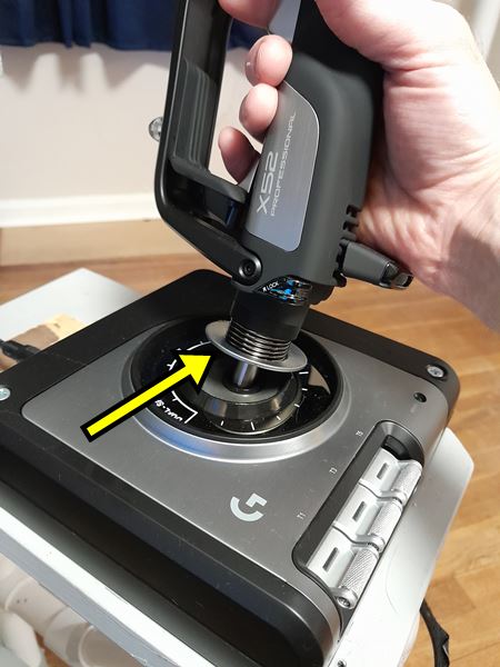
I bought a brand new X52 Pro joystick and discovered it is way too loose in the center of the joystick travel where the spring tension is the weakest. The weak spring tension causes the pilot to overshoot control inputs right where they need to make precise adjustments. Fortunately, TerraVestra’s Spring Plate kit was the remedy I needed. The kit is inexpensive, 3D printed, easy to install, and made in the USA.
How to Install the Logitech Saitek X52 Joystick Spring Mod
The kit includes four spacers of different widths that correspond to four different spring tensions. I used the 5mm wide spacer, which is the widest. If you need more spring tension than that, you can also stack the spacers on top of each other. The spacers fit on both the Logitech X52 and the X52 Pro. The manufacturer includes a handy installation tool. Bonus: this does not void the warranty and you don’t have to disassemble anything.
Here is the installation video, which is also available on their Ebay listing.
Let’s Go Flying!
The increased spring tension helps a lot! The spacer pushes down on the spring which increases tension between the spring plate and the joystick housing. But the increased tension also brings increased friction. I easily remedied this by applying a thin coat of bearing grease to the bottom of the spring plate (see picture). If you don’t have bearing grease, try lithium grease. Lithium grease is probably better for plastic anyway.
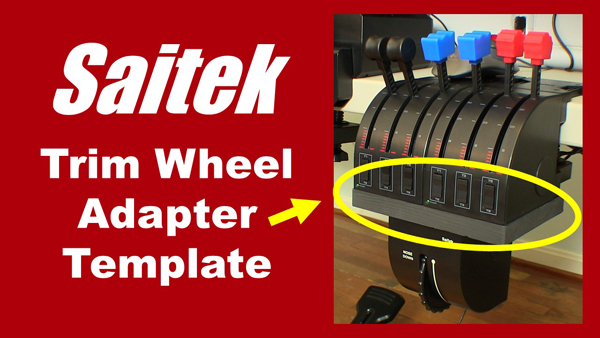
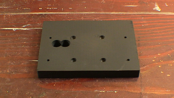
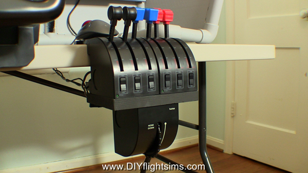
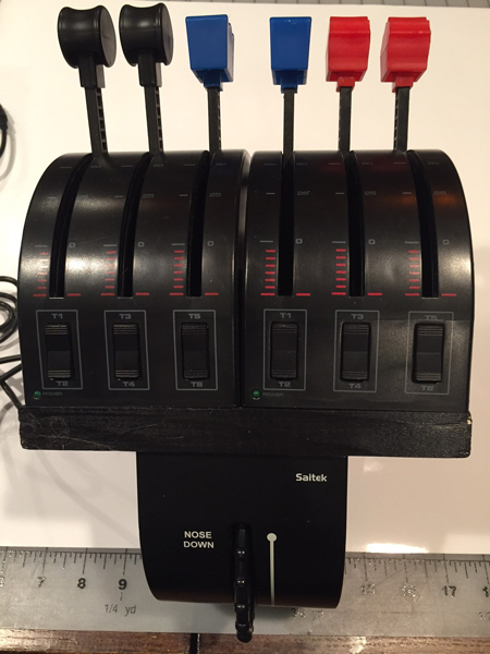
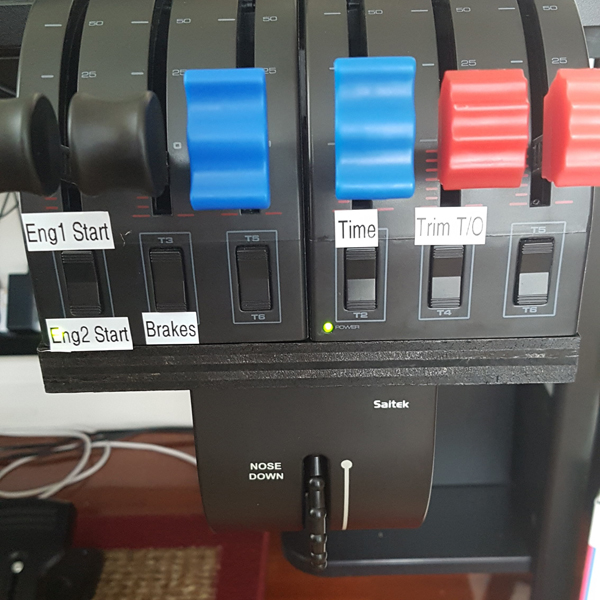
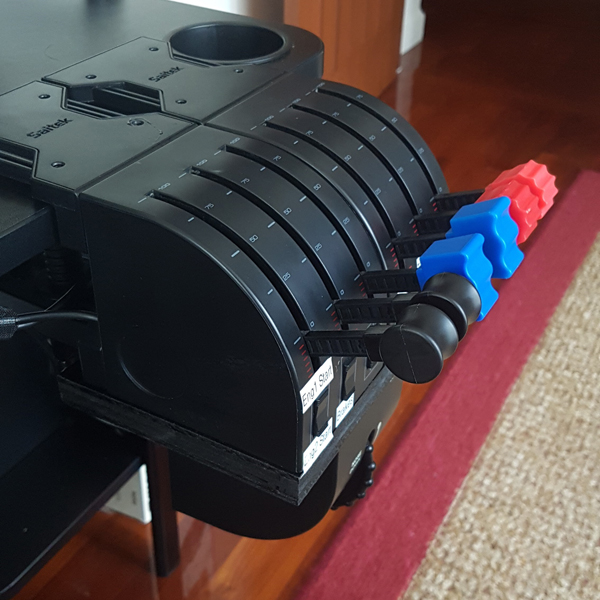
You can install the Saitek Trim Wheel underneath dual Saitek Throttle Quadrants… but only if you use an adapter plate. I made instructions, a DIY video, and a template to help you build a Saitek Trim Wheel Adapter just like the one you see in the pictures.
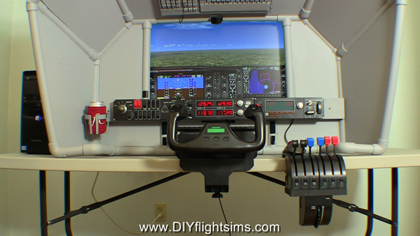
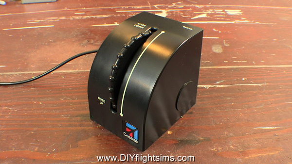
I’m very happy with the Saitek Trim Wheel mainly because proper elevator trim is such a vital and basic skill in real flying. We are lucky that an inexpensive and robust trim wheel is readily available for our home flight simulators. Unfortunately, there is no way to clamp the stock Saitek Trim Wheel to a reasonable location. Believe me, I tried. A pilot should be able to adjust the elevator trim without looking for it the trim wheel. As a result, most trim wheels in real airplanes are located under the throttle or next to the pilot seat. Therefore, I made this Saitek Trim Wheel Adapter plate so you can install your trim wheel in a very natural location for your home flight simulator.
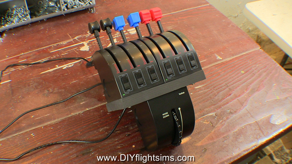
Saitek Throttle Quadrant with Trim Wheel
Install the Saitek Trim Wheel under the Throttle Quadrant
Saitek Trim Wheel Adapter painted black
Saitek Trim Wheel Adapter Template
Saitek Trim Wheel Adapter for your home simulator cockpit
Saitek Trim Wheel
You Can Build a Saitek Trim Wheel Adapter
Take a look at these two examples of Saitek Trim Wheel Adapters built by Flight Sim enthusiasts just like You! Most noteworthy, you will see their Adapters look exactly like the one I built. They used the exact same build template that I offer free on my website. Many thanks to builders Dennis and Ben for sending me their pictures. I would love to see your finished Adapter too. If you build one, please send me pictures of your project to diyflightsims@rogerdodger.net.
Saitek Trim adapter by Dennis
Saitek Trim adapter by Ben (1)
Saitek Trim adapter by Ben (2)
Download the Free Template
Build your own Saitek Trim Wheel Adapter. Start by downloading and printing out the template. Get the template free by signing up for my monthly newsletter, the Roger Dodger Insider. You will be the first to know about product updates, sales, building tips, and more. It’s a monthly email so you won’t be bombarded with a bunch of stuff in your inbox and you can unsubscribe at any time. Become a Roger Dodger Insider here.
This rubber band modification is the simplest and cheapest way to improve the feel of this particular yoke. Welcome to the Saitek Pro Flight Yoke Fix: Rubber Bands.
Before we start, we’re assuming you’ve already removed the pitch spring and swing arms asshown in the disassembly video. Also, I recommend leaving the roll return spring in place. This modification is specifically for the pitch axis.
NOTE: modifying the Saitek yoke will void the warranty. However, if you purchased the yoke over two years ago, the warranty has already expired.
The first issue we should address is the use of rubber bands. Some people won’t use them because they fear the rubber bands will break someday. Yes, there is that possibility, especially if you use old rubber bands. So buy new ones. This bag of rubber bands cost less than one US dollar and they should last a long time. They will definitely last longer than reusing old rubber bands you have sitting around your home or office.
Credit for this Saitek Pro Flight Yoke fix should go to Tom Gromko who published this method on the AVSIM forum.
Rubber Band Installation
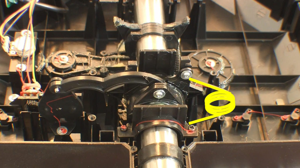
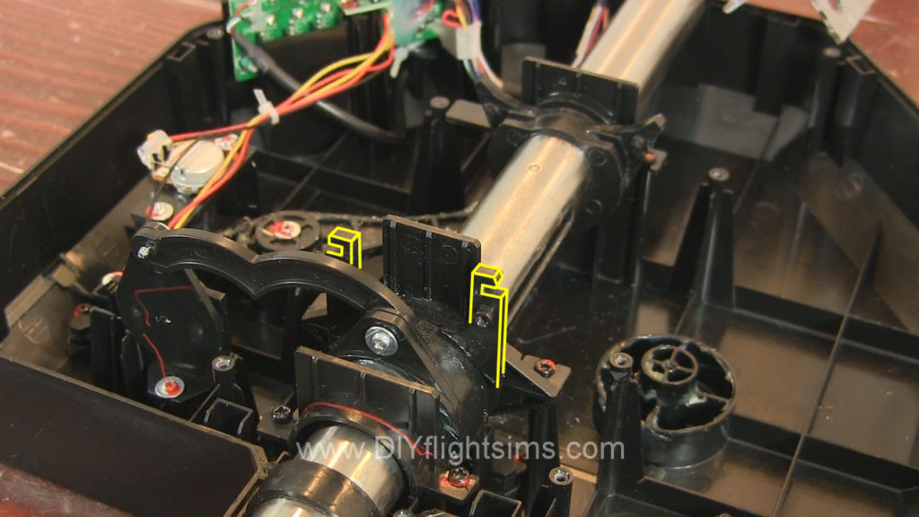
As we get started, note the Saitek yoke has these two tabs that bridge the center shaft. Also locate these horns on the center shaft. I used five rubber bands for this modification, and here’s the first one. Wrap it around the horns and the front tab.
The second one goes around the rear tab and the horns. Try not to twist it much. The third is same as the first, and here’s the fourth. Also push down the rubber bands around the horn. The last rubber band will hold the others in place. Wrap it tightly around the horns.
Test The Control Tension
Now try it out. There is no abrupt detent in the middle of the pitch travel. You can make subtle pitch changed easily. Try the full travel of the controls. Notice it looks like the rubber band may slip off the rear tab. No worries. Recall that these tabs will fit into these slots on the bottom lid. This will keep the rubber bands secure. These tabs may be a little bent out of alignment because of the tension from the rubber bands. This can make it challenging to get the lid back on the control housing. You may need to wiggle the tabs a little to better align them with the slots on the lid.
You can try out the feel of the yoke now. Hold it down with one hand. Note how easy it is to make small pitch changes when you don’t have to struggle against that center detent. If you’re happy with the results, reattach the control housing. There are 14 screws.
And then go flying to test out your new modification!
Saitek Pro Flight yoke fix: rubber bands
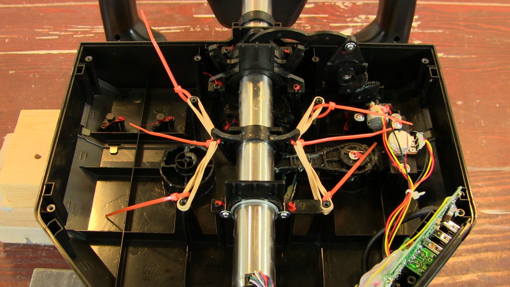
Inexpensive rubber band fix for the Saitek Pro Flight yoke
Wrap rubber bands around these “horns” on the control shaft
Welcome to the Saitek Pro Flight Yoke: Replace Roll Spring instruction video. This modification will replace the roll return spring with rubber bands. Most people don’t have an issue with the roll action of the Saitek yoke, but if you do, this mod is for you. Before we start, I’m assuming you’ve already removed the roll return spring as shown in this disassembly video.
NOTE: modifying the Saitek yoke will void the warranty. However, if you purchased the yoke over two years ago, the warranty has already expired.
Also be sure to use a new rubber band. This bag of rubber bands cost less than $1.00 USD. You’ll only need one, but it’s worth it to know your modification will last a long time.
Saitek Pro Flight Yoke: Replace Roll Spring
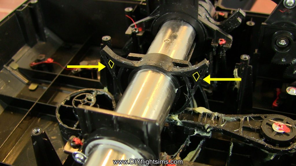
Let’s start by looking at a very interesting structure inside the Saitek yoke housing. Locate the roll return horns as shown in the video and the picture below. Notice as I roll the yoke from left to right, these two horns extend to the left or to the right. It should be pretty easy to loop a rubber band around these horns and let the rubber band provide tension. Select one rubber band. Loop it over three times. Now loop one mini zip-tie through, but do not tighten it all the way. Repeat with another mini zip-tie.
Now simply loop one zip tie over one of the horns. Make sure the zip-tie gets underneath this catch. Tighten down the zip-tie all the way. And repeat with the other zip-tie on the other side. Clip the excess from both zip-ties. The rubber band is now providing tension for the roll axis of the yoke. The rubber band should be secure in its place and should not fall off when we turn the unit over.
Replace the lid and carefully turn it over. Hold the control housing down with one hand. Try it out to see how you like the feel of the yoke now. The rubber band provides a slightly smoother feel. If you’re happy with the results, reattach the control housing. There are 14 screws.
This modification to the Saitek Yoke Pro Flight Yoke uses rubber bands and zip ties. In some respects, it’s similar to the method I used for modifying the yoke from CH Products. This is the modification I personally use with my Saitek yokes. Notice that both yokes have this horn-shaped structure on the center shaft. That’s what we will be modifying. We will also be using these four screw posts. The Saitek Pro Flight Yoke Modification: Rubber Bands and Zip Ties only takes a few minutes to complete.
NOTE: modifying the Saitek yoke will void the warranty. However, if you purchased the yoke over two years ago, the warranty has already expired.
Before we start, we’re assuming you’ve already removed the pitch spring and swing arms as shown in the disassembly video. You can leave the roll return spring in place for this mod, or if you want less resistance, you can remove it.
Rubber Bands? Yes.
Should you really use rubber bands to modify the yoke? Some people won’t use them because they fear the rubber bands will break someday. Yes, there is that possibility, especially if you use old rubber bands. So buy new ones. This bag of rubber bands cost less than one US dollar and they should last a long time. They will definitely last longer than reusing the old rubber bands you have sitting around your home or office.
Let’s start by rotating the yoke so the back of the control housing is facing you. It’s best to prop up the yoke on some boards or something. Locate these horns on the center shaft. And specifically locate this small gap in the plastic structure. Use a drill and an 1/8” drill bit to make a hole right through that small gap. Repeat on the other side. A 1/8” hole should be large enough for these mini Zip Ties.
Next, select four rubber bands and four Zip Ties. Double over the rubber band like this and then loop through and attach a Zip Tie. Repeat for the remaining pairs of rubber bands and Zip Ties. I’ve sped up the video now, but feel free to take your time with this step. The only purpose for these four Zip Ties are to help you handle the rubber bands. They will be cut off later.
Install the Rubber Bands
Here, we have attached the rubber bands and zip ties to one side of the center shaft. Here’s how we did it. Select an additional Zip Tie and thread it through the hole you drilled. Take one of the looped rubber bands and put it over one end of the Zip Tie. Select another looped rubber band and put it over the other end of the Zip Tie, and then attach the Zip Tie to itself, but do not tighten it all the way down yet. Now loop one rubber band over the rear screw post. Loop the other rubber band over the front screw post.
We’re almost finished with the Saitek Pro Flight Yoke Modification: Rubber Bands and Zip Ties. Tighten the middle Zip Tie all the way. Carefully clip off the four extra Zip Ties and also trim the extra length from the middle Zip Ties.
Replace the lid and try it out.
There is no abrupt detent in the middle of the pitch travel. You can make subtle pitch changed easily. If you’re happy with the results, reattach the control housing. There are 14 screws.
And give it a test flight! I hope the Saitek Pro Flight Yoke Modification: Rubber Bands and Zip Ties worked well for you. Happy landings!
Inexpensive rubber bands and zip ties for this mod
It’s easy to mount the Oculus Rift sensor on a tripod.
The Oculus Rift sensor is designed to sit on a desk or table, but sometimes it is much more convenient to mount the sensor on a tripod. For example, my flight simulator does not have a table sitting in front of but this tripod works nicely. It’s easy to mount the sensor on a tripod, I’ll show you how.
This is an old, spare tripod that I wasn’t using any more. You can see where I repaired the crank many years ago. I’ll use this tripod for my Oculus Rift now.
Quick note: You’ll notice I covered the Rift sensor. I did that because the sensor is quite sensitive to bright light and I’m using some pretty bright lights to film this video. You probably won’t need to worry about covering the sensor like I did.
Instructions
If you currently use the Oculus Rift with the sensor sitting on a desk, take a moment to measure the distance from the floor to the sensor. Unclip the wire and let’s take a look at the base of the stand. The base will not unscrew here… look farther up toward the sensor. This is where it unscrews. That’s actually a lot better for us than unscrewing the base. Remove the quick release plate from the tripod. Screw the sensor onto the plate. The threads should match perfectly. Both the sensor and the plate have standard quarter-twenty threads. Return the quick release plate to the tripod. Adjust the height so the sensor is the same distance from the floor as it was before. If you need to re-calibrate the location of the sensor, you can do that in the Oculus Rift software. I recommend using some small strips of Velcro to attach the wire to the tripod.
Simply position the sensor so it points at your headset and take off ! ! !
My joystick, throttle and rudder pedals are secured in place with a framework of PVC pipes and lumber. It is item F311, the Side Joystick Frame and I can help you build one for yourself.
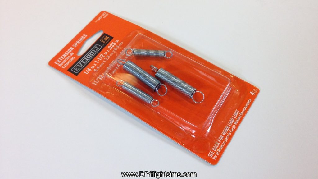
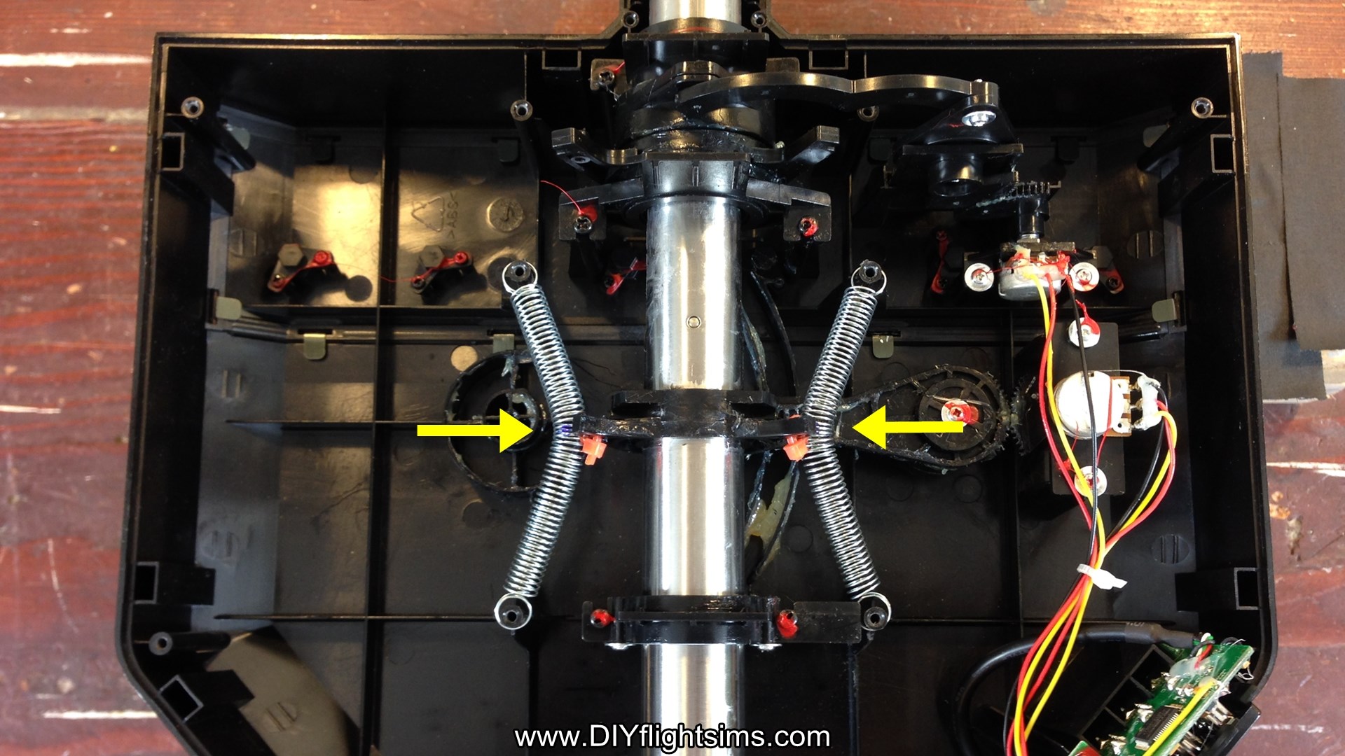
This modification to the Saitek Pro Flight Yoke uses zip ties and springs that I bought from a home improvement store. It’s a very popular modification that I’ll call the Saitek Pro Flight Yoke Ultimate Fix. The springs will attach to the center shaft and the four screw posts.
NOTE: modifying the Saitek yoke will void the warranty. However, if you purchased the yoke over two years ago, the warranty has already expired.
Credit for this idea should go to Tom Gromko who published this method on the AVSIM forum.
Springs for the Saitek Yoke
Before we start, I’m assuming you’ve already removed the pitch spring and swing arms as shown in the disassembly video. You can leave the roll return spring in place for this mod, or if you want less resistance, you can remove it. You’ll notice that I’ve removed it for this video.
The springs we are using are from Home Depot and it costs less than $4.00 USD. This package comes with four springs, but we will only use the larger two. If you can’t find these springs exactly, find ones with a similar load limit – about 2.4 pounds.
Let’s get started. Rotate the yoke so the back of the control housing is facing you and it’s best to prop up the yoke on some boards or something. Locate these horns on the center shaft and specifically locate this small gap in the plastic structure. Use a drill and a 1/8” drill bit to make a hole right through that small gap and then repeat on the other side.
A 1/8” hole should be large enough for these mini Zip Ties to fit through them. The springs will loop over the screw posts on the left side and the right side and then attach to the center shaft. Unfortunately, the springs tend to slide off of the screw posts while we’re working with them, so use a small file to create a groove in the plastic. This file is actually three-sided, therefore it’s really handy for this job. This groove we’re making faces the back of the yoke. For this screw post, file a groove on the front side, towards the yoke handle. The spring stretches easily between the posts and it fits nicely in the groove.
When you work on this post, be very careful not to damage the circuit board or any wiring here so it’s ok to take your time with this step.
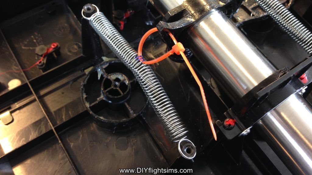
Install Replacement Springs
Now we want to attach the horn on the center shaft to the exact center of the springs. I used calipers to determine the middle point of the spring. You don’t have to use calipers, you can measure carefully or you can even count the strands on the spring to determine the middle. Mark the middle three strands with a sharpie and then remove the spring. The spring can be a little hard to hold on to, consequently, use a zip tie to hold the ends while you fold it over like this.
Look for the mark you made and use a small screwdriver to loop under those three strands on the spring. Then, loop a zip tie under those same three strands and remove the screwdriver. This green zip tie was just temporary and we’re going to cut it off now.
Stretch the spring between the two screw posts again and loop the zip tie through the hole you drilled in the horn and then attach the zip tie like this. Repeat this process on the other side. Now tighten both zip ties all the way and clip off the excess from the zip ties.
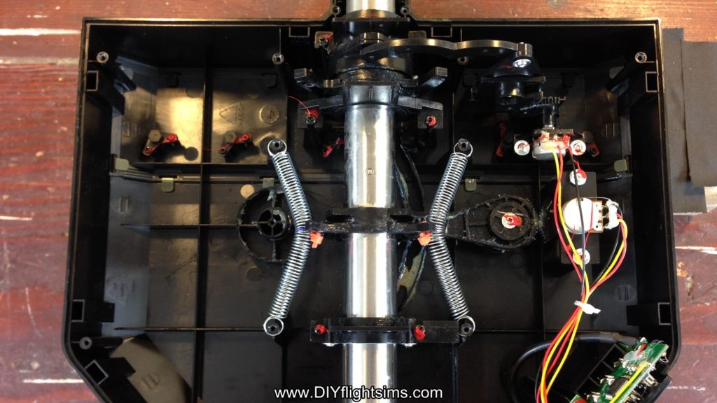
Finishing Steps for the Saitek Pro Flight Yoke Ultimate Fix
Finally, replace the lid and try it out.
Hold down the yoke housing with one hand. Note how easy it is to make small pitch changes when you don’t have to struggle against that center detent. You may notice some noise coming from the springs if you are making large control inputs. But if you’re otherwise happy with the results, reattach the control housing. There are 14 screws.
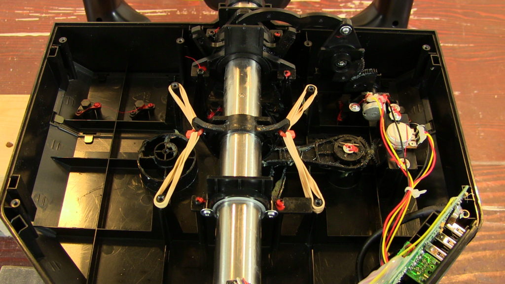
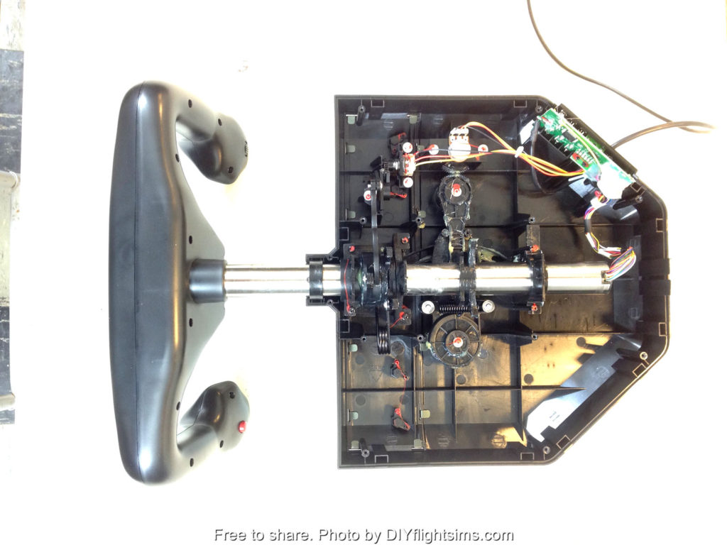
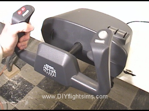
I’ve developed several ways to modify the Saitek Pro Flight Yoke, but first we need to open it up without damaging it or losing parts. Prepare to see inside the Saitek Pro Flight Yoke!
Saitek Yoke Disassembly
This is the very popular Saitek Pro Flight Yoke. This video will demonstrate how to take apart the control housing. You will also see how to remove parts of the pitch and roll mechanisms. We will then be able to modify and improve the pitch and roll movements in later videos.
Note: Disassembly of the Saitek yoke will void the manufacturer’s warranty. However, if you bought the yoke over two years ago, the warranty has already expired.
Let’s get started. Disconnect the yoke from your computer and then turn it upside down on a table. There are 12 screws that hold on the bottom of the control housing. Carefully loosen all of these screws. There are also 2 tiny screws at the base of the control shaft. Remove these and be careful not to lose them. Remove the bottom of the control housing. Most of the screws will probably remain in the housing, and that’s fine. That will save you the trouble of replacing them later.
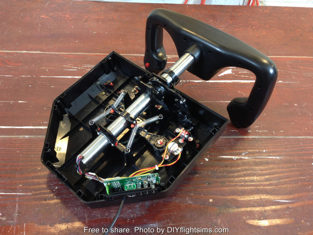
See Inside the Saitek Pro Flight Yoke
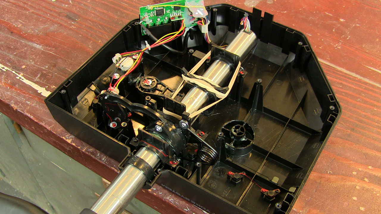
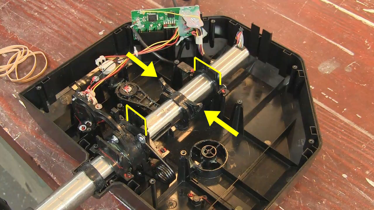
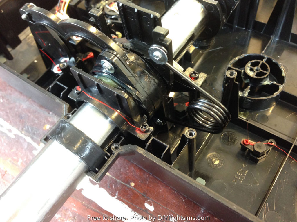
Let’s look at the major components of the yoke. Here is the spring that returns the yoke to its center pitch position. This spring and associated mechanism is what makes the yoke feel like it has a detent. It makes fine pitch adjustments difficult. Even if you’re trying to make small, precise pitch adjustments, you still have to overcome the full tension of this spring. We’re going to get rid of it. Let’s look at some of the other components. This is the pitch potentiometer over here and the potentiometer for the roll movement is here. Here’s another view of the roll movement. This is the roll return spring. This spring is not as objectionable as the pitch return spring, but we will show you how to remove it anyway.
Pitch Axis
Let’s get to work on that nasty pitch return spring. Remove the screw from one side of the spring. The spring is under tension, so carefully unhook it from the post and remove the other screw. Now we see there is actually a second spring underneath the first one! The pitch spring is connected to two swing arms and the swing arms come together at this elbow. Remove this pivot screw (this is where your hands get greasy). Reach in and hold the control arm steady with your left hand and then use your right hand to pull up on the elbow to remove it from its seat. The swing arms are held in tension by the spring, so you’ll need to unhook them from the spring also. Remove both swing arms and then you will see that nasty spring. Verify the control arm is still attached and is still moving the pitch potentiometer. The yoke now moves freely forward and back with no centering feature at all as a result, it is prepared for whatever modification you would like to make.
Roll Axis
The roll movement on the Saitek yoke is not nearly as problematic as the pitch. However, if you still wish to modify it, here is how you remove the return spring. The return spring is held in place with only two screws. The top screw is easy to reach with a small screwdriver. The spring is under tension so carefully unhook it from the mounting post. Turn the yoke all the way to the left. The bottom screw is here, but it’s hard to reach. It’s not a straight shot, but you can still reach it with a small screwdriver so carefully loosen the bottom screw. Be careful not to round out the head of the screw. Remove the screw and the spring from the control housing. Now there are no centering mechanisms for either the roll axis or the pitch axis.
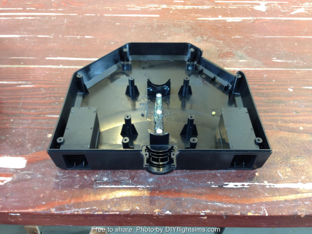
Reassembly
After you’ve completed your modification, you will need to reattach the bottom of the control housing. There are three tabs that must fit into three slots on the bottom of the housing. If you don’t have all three tabs aligned with the slots, the housing won’t fit. Sometimes it takes some wiggling to get the housing to fit correctly. There is also a tab at the back of the housing that must fit inside the lip. Now you know how to take apart the Saitek yoke and how to put it back together again. The remaining videos in this series will show several ways to modify and improve the yoke.
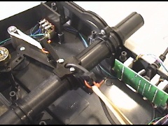
Below are some high-resolution photos of the major components inside the Saitek Pro Flight Yoke….
How to disassemble the Saitek Pro Flight Yoke
Pitch potentiometer
Major interior components of the Saitek Pro Flight Yoke
This is the CH Products Flight Sim Yoke. I’m going to disassemble it to show all the hackers and makers what to expect if they ever want to modify one.
Note: This will void the manufacturer’s warranty, but if you bought the yoke over a year ago the warranty has already expired.
Start by popping off the knob handles from the little mini-levers. Unscrew the table clamps, so now you have access to this corner screw. The screws in the opposite corners are under the rubber stoppers. Also there’s a screw under the warranty sticker of course. There are 8 screws total.
Now we’ve re-attached the table clamps and removed the top in order to show the inner workings of the control housing. Be careful that the back of the shaft doesn’t pop up. There’s a lever underneath the shaft, and this links to the pitch potentiometer. Note you will need to verify it’s seated correctly when you re-assemble the housing later. Here’s the linkage for the pitch potentiometer. Note that the pitch trim wheel moves the potentiometer too. The trim is way too sensitive to be useful, as a result, I just forget about it and use the Saitek trim wheel (which is great).
Additional Observations
The roll movement is linked to the other potentiometer at the back of the unit. If you have a separate throttle quadrant (and I hope you do), these mini-levers on the top of the housing become redundant. You can remove these 6 screws and the wiring clip to take out this component. The yoke grip can be disassembled if you’re adding buttons, or something similar. There are 10 screws total in the grip.
Once the face is off, you can see all the wires from the various buttons. The wires snake through the shaft and come out here. The centering springs return the yoke to its middle position for pitch and roll. Most noteworthy, these springs, plus the friction of the control shaft can make it difficult to make subtle control movements like during a landing flare. Click to this blog post and video to see how to fix the CH Products Yoke to avoid over-controlling your home flight simulator.
The CH Products Flight Sim Yoke is a solid addition to your home flight simulator. Even so, we can modify it a little to make the yoke work more smoothly because the spring tension and the friction within the mechanism can cause you to over-control the airplane. Sometimes you need to make more subtle control inputs.Ideally, when you have the airplane trimmed properly, you can fly with a light touch on the yoke. For example, if you’re over-controlling the airplane during landing, you’ll porpoise down the runway. Well if you don’t do that in real life, it’s embarrassing when it happens in flight simulator.
Our previous video showed how to disassemble the yoke. This video will show the CH Products yoke modification. I’m basically replacing the tension springs with rubber bands. The mod is reversible, so if you decide you don’t like it, you can change it back to the way it was before.
CH Products Yoke Modification
Note: disassembling consumer products may void the manufacturer’s warranty.
We will start by removing the springs. There is continuous tension on the spring, so push it down onto the pylon. Then remove the screw and washer… and carefully unhook the spring. Reattach the screw. Unhook the other end of the spring from the shaft. Repeat on the other side to remove the second spring. This cable is held in place with a small zip tie. Carefully snip it off. We’re going to use the hole that the zip tie was in…but we’re going to need one on the other side too. Here’s the existing hole, and now we’re drilling one in the same place on the other side. This is a one eighth inch drill bit. Just removing the little plastic shavings here.
Now we have our own little zip ties for the next step, and rubber bands. Insert the zip tie through the hole. Take two rubber bands and loop them over themselves like this. Connect the zip tie to one end of the rubber bands like this. Then stretch the rubber band over the pylon. Repeat on the other side. Notice I’m holding the yoke handle when I loop the rubber bands over the pylon.
Everything is looking good so far so let’s tighten up the zip ties. Loosen the rubber bands, cinch up the zip tie, then loop the rubber bands over the pylon again. Here’s the opposite side. Try not to get the rubber bands twisted too much. Snip off the ends of the zip ties.
Finishing Steps
Now you might ask, isn’t there a simpler way? If you look at how the shaft is constructed, you’ll notice we can simply loop these rubber bands on the opposite horn like this and loop the other rubber bands on the other side. Well that does work, but not very well. The rubber bands tend to rub against each another and make a banjo sound. I’m assuming you don’t want your yoke to sound like a banjo, so that’s out.
Remember this lever needs to be seated correctly on the bottom of the shaft, and the sleeves need to set in the grooves on the back of the unit. Finally, this wiring harness was disconnected from the mini-levers that we removed in the previous video. We don’t want it flopping around, so we attached it to these other wires with a zip tie, and everything is tucked away nicely.
The CH Products yoke modification is complete! Now the yoke has a better response to those subtle little control inputs that we tend to use when the airplane is trimmed for cruise flight, or any time a soft touch is necessary.


Recent Comments