Saitek Pro Flight Yoke Ultimate Fix

This modification to the Saitek Pro Flight Yoke uses zip ties and springs that I bought from a home improvement store. It’s a very popular modification that I’ll call the Saitek Pro Flight Yoke Ultimate Fix. The springs will attach to the center shaft and the four screw posts.

NOTE: modifying the Saitek yoke will void the warranty. However, if you purchased the yoke over two years ago, the warranty has already expired.

Credit for this idea should go to Tom Gromko who published this method on the AVSIM forum.

Springs for the Saitek Yoke

Before we start, I’m assuming you’ve already removed the pitch spring and swing arms as shown in the disassembly video. You can leave the roll return spring in place for this mod, or if you want less resistance, you can remove it. You’ll notice that I’ve removed it for this video.

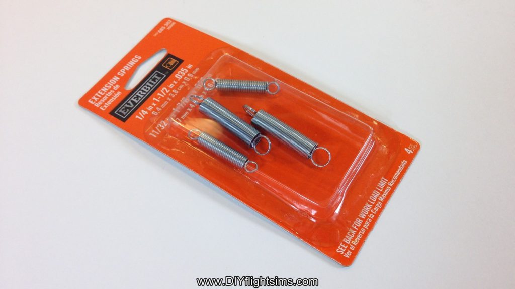
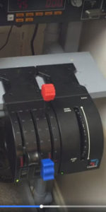
The springs we are using are from Home Depot and it costs less than $4.00 USD. This package comes with four springs, but we will only use the larger two. If you can’t find these springs exactly, find ones with a similar load limit – about 2.4 pounds.

Home Depot Extension Springs
Store SKU 685383
Model # 16086
Internet # 202045462

Modify the Control Horns

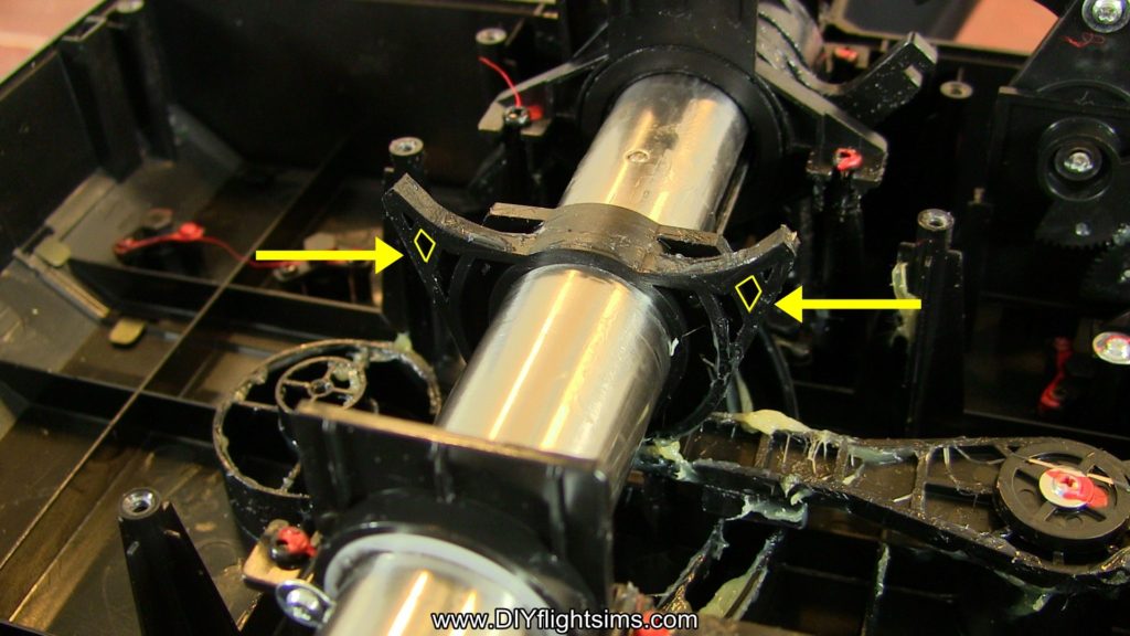
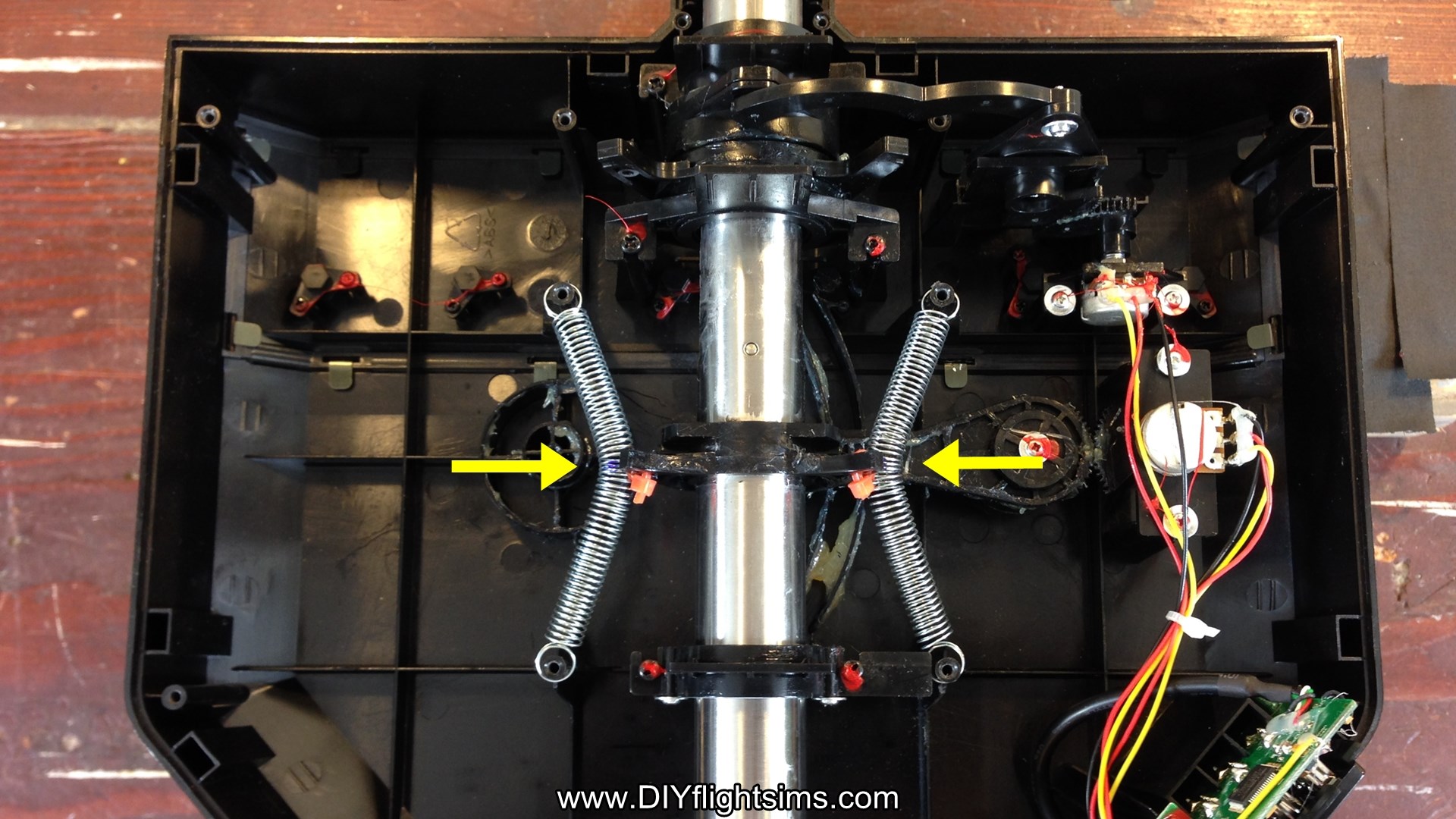
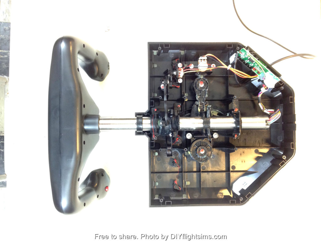
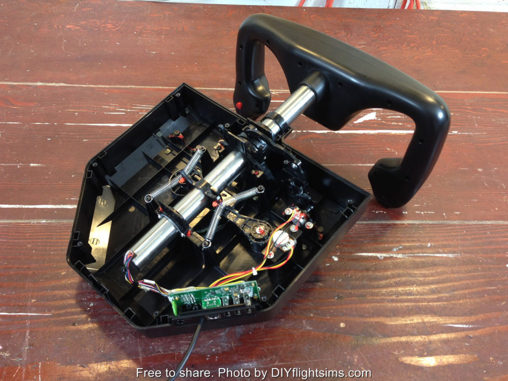
Let’s get started. Rotate the yoke so the back of the control housing is facing you and it’s best to prop up the yoke on some boards or something. Locate these horns on the center shaft and specifically locate this small gap in the plastic structure. Use a drill and a 1/8” drill bit to make a hole right through that small gap and then repeat on the other side.

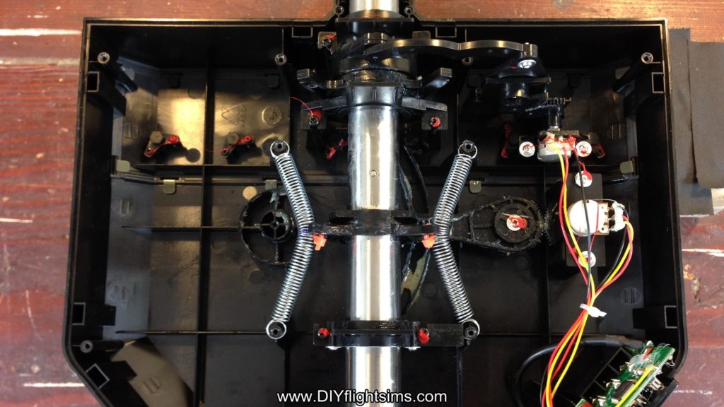
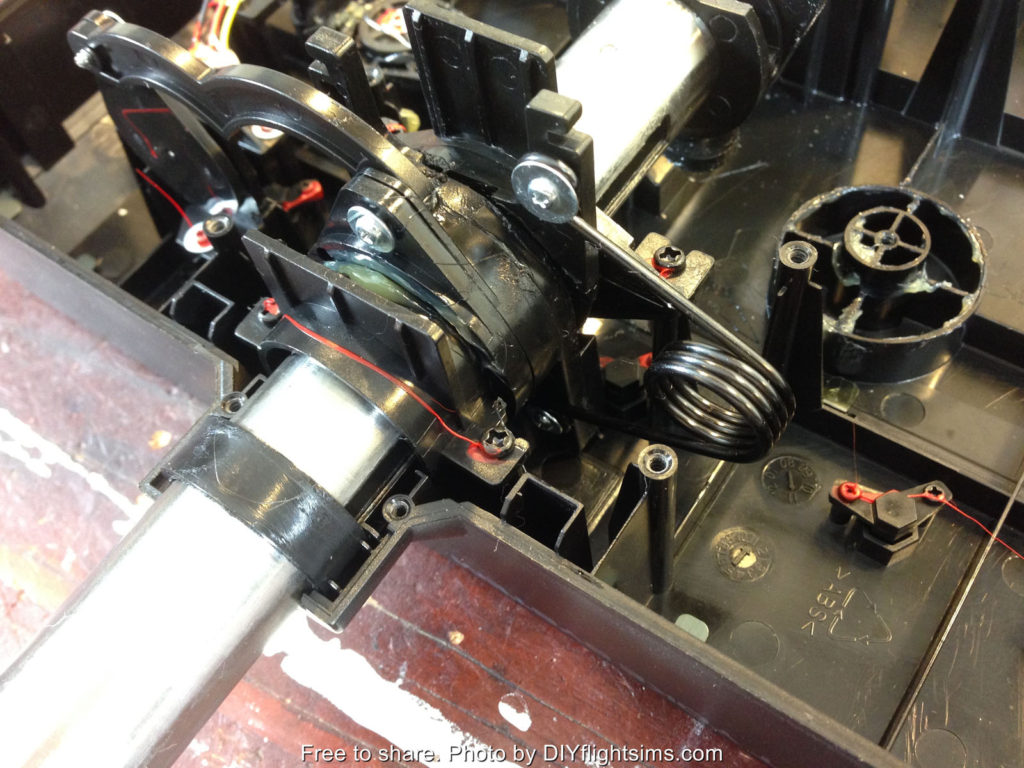
A 1/8” hole should be large enough for these mini Zip Ties to fit through them. The springs will loop over the screw posts on the left side and the right side and then attach to the center shaft. Unfortunately, the springs tend to slide off of the screw posts while we’re working with them, so use a small file to create a groove in the plastic. This file is actually three-sided, therefore it’s really handy for this job. This groove we’re making faces the back of the yoke. For this screw post, file a groove on the front side, towards the yoke handle. The spring stretches easily between the posts and it fits nicely in the groove.

When you work on this post, be very careful not to damage the circuit board or any wiring here so it’s ok to take your time with this step.

Install Replacement Springs

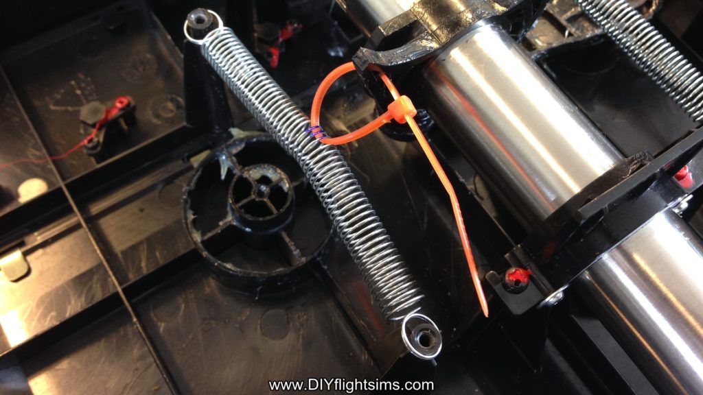
Now we want to attach the horn on the center shaft to the exact center of the springs. I used calipers to determine the middle point of the spring. You don’t have to use calipers, you can measure carefully or you can even count the strands on the spring to determine the middle. Mark the middle three strands with a sharpie and then remove the spring. The spring can be a little hard to hold on to, consequently, use a zip tie to hold the ends while you fold it over like this.

Look for the mark you made and use a small screwdriver to loop under those three strands on the spring. Then, loop a zip tie under those same three strands and remove the screwdriver. This green zip tie was just temporary and we’re going to cut it off now.

Stretch the spring between the two screw posts again and loop the zip tie through the hole you drilled in the horn and then attach the zip tie like this. Repeat this process on the other side. Now tighten both zip ties all the way and clip off the excess from the zip ties.

Finishing Steps for the Saitek Pro Flight Yoke Ultimate Fix

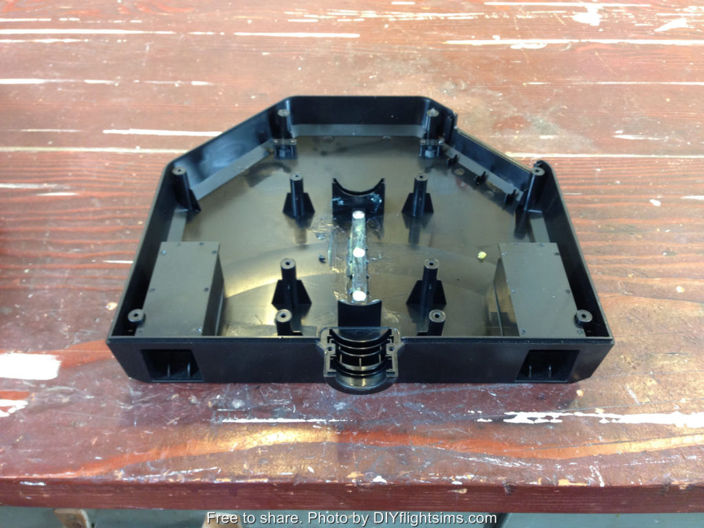
Finally, replace the lid and try it out.

Hold down the yoke housing with one hand. Note how easy it is to make small pitch changes when you don’t have to struggle against that center detent. You may notice some noise coming from the springs if you are making large control inputs. But if you’re otherwise happy with the results, reattach the control housing. There are 14 screws.

And give it a test flight!

Saitek Pro Flight Yoke Modification Videos


Saitek Pro Flight Yoke Ultimate Fix

See Inside the Saitek Pro Flight Yoke

I’ve developed several ways to modify the Saitek Pro Flight Yoke, but first we need to open it up without damaging it or losing parts. Prepare to see inside the Saitek Pro Flight Yoke!

Saitek Yoke Disassembly

This is the very popular Saitek Pro Flight Yoke. This video will demonstrate how to take apart the control housing. You will also see how to remove parts of the pitch and roll mechanisms. We will then be able to modify and improve the pitch and roll movements in later videos.

Note: Disassembly of the Saitek yoke will void the manufacturer’s warranty. However, if you bought the yoke over two years ago, the warranty has already expired.

Let’s get started. Disconnect the yoke from your computer and then turn it upside down on a table. There are 12 screws that hold on the bottom of the control housing. Carefully loosen all of these screws. There are also 2 tiny screws at the base of the control shaft. Remove these and be careful not to lose them. Remove the bottom of the control housing. Most of the screws will probably remain in the housing, and that’s fine. That will save you the trouble of replacing them later.

See Inside the Saitek Pro Flight Yoke

Let’s look at the major components of the yoke. Here is the spring that returns the yoke to its center pitch position. This spring and associated mechanism is what makes the yoke feel like it has a detent. It makes fine pitch adjustments difficult. Even if you’re trying to make small, precise pitch adjustments, you still have to overcome the full tension of this spring. We’re going to get rid of it. Let’s look at some of the other components. This is the pitch potentiometer over here and the potentiometer for the roll movement is here. Here’s another view of the roll movement. This is the roll return spring. This spring is not as objectionable as the pitch return spring, but we will show you how to remove it anyway.

Pitch Axis

Let’s get to work on that nasty pitch return spring. Remove the screw from one side of the spring. The spring is under tension, so carefully unhook it from the post and remove the other screw. Now we see there is actually a second spring underneath the first one! The pitch spring is connected to two swing arms and the swing arms come together at this elbow. Remove this pivot screw (this is where your hands get greasy). Reach in and hold the control arm steady with your left hand and then use your right hand to pull up on the elbow to remove it from its seat. The swing arms are held in tension by the spring, so you’ll need to unhook them from the spring also. Remove both swing arms and then you will see that nasty spring. Verify the control arm is still attached and is still moving the pitch potentiometer. The yoke now moves freely forward and back with no centering feature at all as a result, it is prepared for whatever modification you would like to make.

Roll Axis

The roll movement on the Saitek yoke is not nearly as problematic as the pitch. However, if you still wish to modify it, here is how you remove the return spring. The return spring is held in place with only two screws. The top screw is easy to reach with a small screwdriver. The spring is under tension so carefully unhook it from the mounting post. Turn the yoke all the way to the left. The bottom screw is here, but it’s hard to reach. It’s not a straight shot, but you can still reach it with a small screwdriver so carefully loosen the bottom screw. Be careful not to round out the head of the screw. Remove the screw and the spring from the control housing. Now there are no centering mechanisms for either the roll axis or the pitch axis.

Reassembly

After you’ve completed your modification, you will need to reattach the bottom of the control housing. There are three tabs that must fit into three slots on the bottom of the housing. If you don’t have all three tabs aligned with the slots, the housing won’t fit. Sometimes it takes some wiggling to get the housing to fit correctly. There is also a tab at the back of the housing that must fit inside the lip. Now you know how to take apart the Saitek yoke and how to put it back together again. The remaining videos in this series will show several ways to modify and improve the yoke.

Below are some high-resolution photos of the major components inside the Saitek Pro Flight Yoke….

Saitek Pro Flight Yoke Modification Videos


See inside the Saitek Pro Flight Yoke

DIY Flight Sim Pod Final Assembly

DIY Flight Sim Pod Final Assembly

DIY Flight Sim Pod Final Assembly Video Transcript

This is an excerpt from the DIY Flight Sim Pod instructional video. The video and associated manual show you every step in building this home flight simulator project.

In this final section, we’re going to populate the Inner Frame with computer hardware. Furthermore, we will assemble all the pieces of the Flight Sim Pod. Your new flight simulator will soon be finished!

We see here the Inner Frame, all painted and masking tape removed, lt’s look at the right side of the frame. Here on the Computer Shelf we can set a desktop computer, and a powerstrip on the Top Shelf.

Next: the monitor or HDTV. It is a very good idea to get help from a friend while mounting the HDTV. You can’t actually see the bracket when you clip onto it, so it helps to have a second pair of eyes watching. Make sure it’s centered in the frame also.

Install the switch panels and then add the yoke, and beside the yoke, the throttle quadrant. I have attached Velcro to the top of the throttle quadrant for the trackball mouse. There is enough room on the yoke housing for a mini-keyboard, or it can go beside the yoke. Don’t forget a drink holder!

Attach the rudder pedals, and add the speakers. Remember the Chair Staytheres? I painted these also. They have Velcro that loops over this horizontal bar. Notice when you use the Chair Staythere you have to reach way down to get it and you might want an easier way. I simply measured 7” from the end of the pipe and drilled two holes and then I tied on a piece of boot string and hung it from the pipe above. I did this on both sides.

Now I don’t have to reach down so far. With all the peripheral equipment on this machine, we end up with a lot of wires. I loop the wires and use strips of Velcro to keep them organized. If I need a USB extension, I use Velcro straps to help keep it secure. Use it for the rudder pedals so the wire won’t get tangled up with your feet. I secured the USB hubs with Velcro too. I recommend labeling the USB wires, there are so many of them

Once everything is hooked up, it’s time for a test drive! Make sure all the peripherals work correctly.

We’re almost finished with the DIY Flight Sim Pod Final Assembly. For the final step, I really recommend you get help from a friend because you’ll need someone to hold the Side Wall in place while you attach it to the three interface points. The first point is near the Side Boards. There are two points in the front that slide into place also

Secure each interface point with a self-drilling screw. That Side Wall will stand by itself so you can attach the other Side Wall. Attach all three interface points with self-drilling screws. Next replace this bottom support pipe, or the tail end extension, your choice. Secure with self-drilling screws.

Carry in the Top Canopy, and set the 1×4 board on the ledge near the top of the support pillars. Have your partner hold the back of the Top Canopy while you attach the front. Once the front two corners are in, you can attach one of the back corners. Secure the front two corners with self-drilling screws.

Now we can attach the top support pipe. First insert it in the left side. Remember, we left the right side of the Top Canopy loose for this reason. Attach both pipes simultaneously. Attach four self-drilling screws: The two back corners of the Top Canopy, and both sides of the top support pipe.

You can build your own DIY Flight Sim Pod with this instructional video and manual

 .

man and woman attach side wall
DIY Flight Sim Pod final assembly

Add a Second Monitor – Part 2

Add a second monitor

Dual Monitors for Flight Simulator

This video will show you how to add a second monitor to your home flight simulator. In Part 1 I modified the monitor mounting bracket and attached it to this 1×8 board. 

Now we will paint the board, install the monitor, and configure Microsoft Flight Simulator X to run on two monitors

Video Transcript

This is where we left off. Now I know all the components will fit correctly, so next I’ll paint the board.

I removed the mounting bracket and all components, but I left the tee nuts in place. I’m painting with tinted primer like I do with all my projects.

After one side has dried, flip it over and paint the other side.

The paint is dry to the touch, but it can still stick to the support boards when it sits overnight so I’m putting a few screws between the boards to allow the paint to dry completely.

I want a layer of masking tape (or something similar) between the new board and this attachment board. If I don’t separate the two boards like this, the paint will stick the boards together almost like glue.

Attach the board with deck screws,

Test fit the monitor to make sure it fits correctly.

You may or may not need an adapter for the monitor cable. This cheap little monitor only has a VGA plug.

Now that the monitor cable and power are hooked up, we can slide the monitor into place and turn on the computer.

The operating system should be smart enough to recognize the second monitor.

If not, right-click the desktop and choose “Screen Resolution” you may need to prompt the operating system to detect the monitors.

I recommend setting the large screen as Display 1

Also select “Extend these displays” here.

You know it’s working correctly if you can drag a window from one monitor to another.

Start Microsoft FSX. For this example, I’ll use the default G1000 Beechcraft Baron.

Select the 2D cockpit view. Right-click just above the instrument panel and select “Close window”

Next, select Shift + 4 to show the Primary Flight Display in a more manageable shape.

Now I can left click and drag it over to the smaller monitor and drag the edges to re-size the window.

Next, do the same thing with the Multi Function Display

I also like to display the Landing Gear Panel because it shows the elevator trim setting. Check out the Saitek trim wheel (I love this thing). Now I can see the trim setting for takeoff.

A quirky thing about this setup is that even if you save the flight, and exit, FSX will not save the locations of the instruments. The next time you start the flight, the instruments will have to be moved and re-sized again. You can remedy this by using Air Manager from Sim Innovations to display the instruments on your second monitor.

If you use TrackIR, a second monitor can still help you. Here I have the Virtual Cockpit on the main screen and the flight instruments on the small monitor. It works quite well.
It was a great experience to add a second monitor to my flight simulator and I hope your project goes well too.

Check out Part 1 of this project if you missed it


Add a second monitor to a flight sim

Add a Second Monitor – Part 1

Dual monitors

Dual Monitors for Flight Simulator

This was a great project and really enhanced the Flight Sim Pod. Dual monitors allow you to display the flight instruments on a smaller screen and show the outside view on a large monitor, or even an HDTV as shown here. Most noteworthy: quality flat panel monitors are wonderfully inexpensive now! 

Video Transcript

You can display your flight instruments on an auxiliary monitor and use your main monitor for the outside view. This increases your outside visibility and makes it easier to read the instruments.

This is nothing new. People have been running flight simulator on multiple monitors for years, but I wanted to show you some specific issues for mounting a second monitor.

I’ll literally show you the nuts and bolts of this process.

Part 2 of this video will show you what to expect when you run Microsoft Flight Simulator X on two monitors.


To start off, I removed the 1×6 board from the flight simulator and used a 1×8 board instead. I needed this taller board to mount these two Saitek switch panels vertically.

If you don’t have a miter saw that can cut a 1×8 board you can usually get that done at the store. Many home improvement stores will cut lumber for you.

Now lets look at the monitor mounting bracket. This small bracket is appropriate for this size monitor. One half of the bracket attaches to the monitor, the other half will attach to the board.

This is the Dell 19 inch monitor that I’m using for this project. It was very inexpensive.

This is how the bracket will fit on the monitor….
but look here: the bottom edge of the monitor can not hang below the bottom edge of the board….

Because, I have to allow room for the Saitek yoke below it.

Unfortunately, that puts the top attachment holes on the bracket too close to the top edge of the board, so we can’t use those holes.

No problem. We will simply drill new holes into the steel bracket!
It’s not difficult. First, I measure where the new holes will be: three quarters of an inch on center, below the existing holes.

Next I tap the center points with a punch and hammer.

I drilled pilot holes first with a 1/8” drill bit. Use cutting fluid if you have it, or a lubricant like WD-40.

Next, use a ¼” drill bit to make the holes larger. Notice that I clamped the bracket in place.

The drill bit generates a lot of heat, so take your time. Drill a little, then back off for a moment to allow the bit to cool. Then repeat.

The drill press I’m using is not expensive or fancy. You could probably even do this with a hand drill if you clamped the bracket to a work bench. Either way, remember to take your time and be safe.

Use a 5/16” drill bit to make the holes larger one last time. So yes, I used three different drill bits for these holes. Yes, there is an easier way, a step bit will allow you drill holes in steel without changing drill bits.

Wear safety glasses. Wear safety glasses. Look, you can actually see bits of hot metal shooting in different directions.

Are dual monitors worth going through all this trouble? Yes! You will love having your flight instruments on a separate monitor.

Be sure to clean up the bracket after you’re done drilling.

Attach the mounting bracket to the back of the monitor according to the manufacturer’s instructions. This model already has mounting screws for this purpose.

The bracket slides on easily.

Measure the distance from the bottom edge of the monitor to the top edge of the bracket. In this case, it’s 7 ½”

I want the monitor in the center of the board, so I’m measuring the halfway point here.

Again, I want the top of the mounting bracket to be 7 ½” above the bottom of the board.

Hold the bracket in place and trace where your four mounting holes will be.

Drill pilot holes with a 1/8” drill bit, then final holes with a 5/16” drill bit

Now we can use ¼-20 screws to attach the bracket…. However, there’s another issue to address.

The ends of these screws will be too close to my 40” HDTV. I’m not comfortable with that.

So I used these ¼” tee nuts for the top two holes.

Flip the board over, and bang in the tee nuts with a hammer and a block of wood.

You can use shorter screws now. 1 inch long ¼-20 screws with washers.

Make sure the bracket is straight and attach ¼-20 screws to the bottom two holes. These screws are an inch and a half long, attach with nuts, washers and lock washers.

Slide on the monitor and see how it fits.

This is how it will sit in relation to the switch panels.

In part 2 of this video, we will paint the board and attach it to the flight simulator. I’ll also show you how to relocate the aircraft instruments to your new monitor in Microsoft Flight Simulator X.


Dual monitors for your home flight simulator
large two screen flight sim

Customer-Built DIY Flight Sim Pod

I love adding pictures to the Customer Gallery! Check out this customer-built DIY Flight Sim Pod that was completed by Russ in North Carolina. He has it set up to simulate general aviation airplanes and regularly uses it for cross-country flights that he posts about on his Facebook fan page. You can see it features a large HDTV as the primary display, an auxiliary monitor for the flight instruments, Saitek switch panels, and the Saitek Pro-Flight yoke/throttle quadrant.

It’s a great build and I would like to point out some details that Russ included that contribute greatly to a quality home flight sim project:

  • He painted it. A lot of people want to skip painting, but it’s such an important part of a truly finished project
  • Note the trackball mouse. I recommend this handy feature for any flight sim.
  • Rudder pedals! No twisty joysticks for us, we’re pilots.
  • Trim wheel: this is a great product from Saitek that I think is overlooked by way too many people in the flight sim community.

Customer-Built DIY Flight Sim Pod

I’m happy to see pictures of a completed DIY Flight Sim Pod. This is one of my favorite projects but after I published it, I started to realize many people probably didn’t have room for a home flight simulator this large. The Pod is about the size of a Smart Car. Russ found a way to work with limited space by leaving off the Pod’s side walls. You can see in his video here that the walls of this room actually serve as the side walls for the flight sim …. smart! 

You can keep up to date with Russ’s flying adventures by liking his Facebook fan page at this link.

Happy landings!