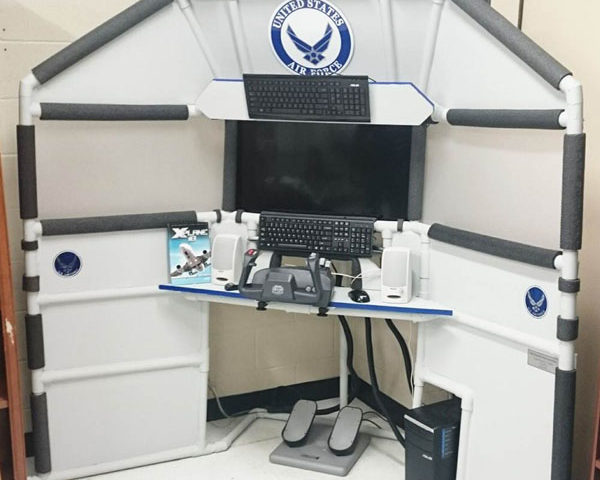
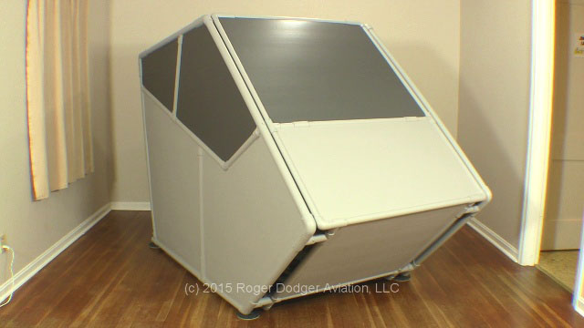
A young man named Ryan built this flight simulator for an Eagle Scout Service project. You might be wondering how a Flight Simulator Eagle Scout Project comes into being. If you are unfamiliar with service projects, the Scout must demonstrate that he has a plan for funding and building the project and he must also show that it’s a benefit to the community.
(Let’s be real: ALL flight simulators benefit the community, but I digress).
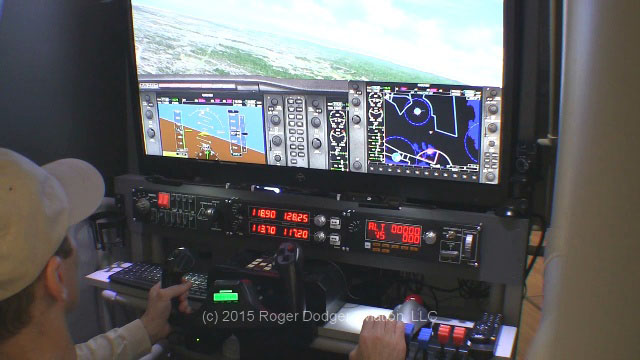
Ryan reached out to me and requested a donation of the T440 Triple Screen Flight Sim project video/manual and I granted his request. He raised enough money or donations to build the DIY flight sim as you see in the picture. He also modified the design to match his resources and needs. After completing the project, Ryan donated it to his Junior Reserve Officer Training Corps (JROTC) classroom. This is the official JROTC for the United States Air Force and the cadets use this flight simulator to learn about flying and careers in the USAF.
Quote from Ryan:
“Thank you so much for your flight sim plan donation for my Eagle Scout Project. As you can see I had to make some changes due to the equipment and available space in the JROTC class room… Thank you for making this project possible through your donation and helping me make the Air Force JROTC program at my high school more fun for the cadets learning about flight.”
Charitable Donations
I get requests regularly from people asking for free stuff, but I rarely fulfill those requests, even from people claiming to represent charitable groups.
There are several reasons I rarely give away free stuff
My videos and instruction manuals are the least expensive part of your project. If you really want to save money, try getting discounts on your displays, computer, or controls.
I do not receive follow-up from the people I donate to 99% of the time. All I ask for is a picture of the completed project and a description of how it’s being used. I have received a follow-up message only two times in nine years and both times they were Eagle Scouts that completed their service projects.
It’s more work for me. I have to manually generate download emails when I fulfill a donation. On the other hand, regular purchases are automatic and instant.
I regularly offer huge sales on all my products. If you sign up for my monthly newsletter, you will be the first to know about upcoming sales.
Roger Dodger Aviation does not make enough money. As long as I have to work at a day job, I probably won’t have the time to seriously consider the donations requests I receive.
Is is time to take the leap into Virtual Reality and incorporate it into your flight simulator? Maybe not, depending on what you like to simulate. In this article I continue my exploration of Virtual Reality for Flight Simulator and discuss Flight Simulator X, War Thunder, some physical and financial issues, and system specs. In Part 1 of this article, I experimented with DCS World and Elite Dangerous in Virtual Reality. You can read it here.
Flight Simulator X with FlyInside and Leap Motion
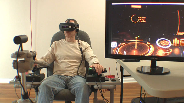
This is the big one! FlyInside FSX is an ambitious project to make Microsoft Flight Simulator X compatible with VR. Leap Motion is an infrared sensor that can detect the location and position of your hands, so you can see your hands in Virtual Reality. Put FlyInside and Leap Motion together and you can activate airplane switches with your hands in the FSX virtual cockpit! If that is difficult to imagine, here is a video that demonstrates it.
Disclaimer: I discovered it’s really difficult to take good screen shots in Virtual Reality for flight simulator, so for this article I borrowed representative pics from other sources. This has no impact on the validity of my findings.
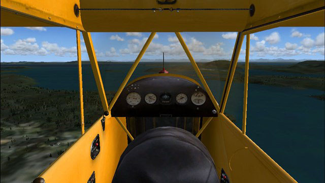
FlyInside FSX is a rather new project and even though it didn’t work for me, I still think it’s important to support the developer. The first flight I tried was the simple default flight around Friday Harbor in a Piper Cub. It was pretty cool to look around in VR, as long as I didn’t move my head too fast. Virtual Reality works best when the images are rendered at 90 frames per second or more. The stock FSX can’t consistently provide fps nearly that fast, but FlyInside has a trick to get around that. Unfortunately, it didn’t work well enough. When I moved my head, the images lagged. Lagging equals motion sickness, remember that. When the images you see with your eyes do not match your head movement, you can get motion sickness very quickly. I’m not prone to motion sickness, so I was able to do a few takeoffs and landings without barfing, but the experience is not nearly as good as VR in other flight sim software. On the other hand, I found that it’s easier, and it feels more realistic to land an airplane in VR.
I tried to trim the airplane during flight, and that’s when it all went sour. Recall that I also used Leap Motion, so I could literally see my hands while flying in the virtual Piper Cub. This is supposed to give me the ability to manipulate controls and switches in the cockpit, much like it’s possible now with the mouse. I reached out to adjust the elevator trim and…. FSX crashed. I re-booted and tried the same thing again… another crash. And that’s it. After two crashes, I’m done.
Conclusion: support this project. I did, but I won’t use it again until it’s more reliable.
War Thunder
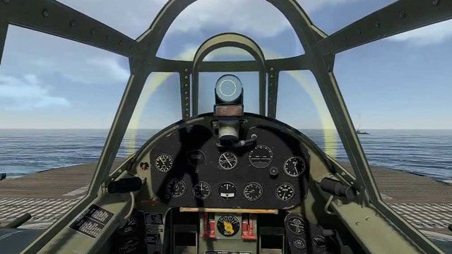
Combat in Elite Dangerous made me miss my old online squadron. I had never played War Thunder before, but it’s free to sign up so I enlisted and went back to World War 2 for the first time in several years. This game was much more menu-friendly to VR than DCS world was. I wasn’t familiar with War Thunder, so it took a while to get my controls and buttons assigned. Apparently, the game isn’t expecting many users to have rudder pedals, so that really throws it for a loop.
Once I had my controls set up, I launched into battle with my pathetic P-26 Peashooter (that’s how you start out). Even with my crappy plane, I had blast in War Thunder. I had a level of spatial orientation that I’ve never had before in a flight simulator. VR is a game changer for air combat because of the way I could look above, below, behind, and around the cockpit frame. Even though I was a rookie, most of the guys in the Arcade level don’t know anything about energy fighting so I was able to use that to my advantage and I leveled-up rather quickly, or at least I think I did. The flurry of levels and tokens and things are still a mystery to me.
War Thunder also has a Realistic mode that I tried, but I didn’t get my controls completely set up. A Saitek X-52 looks nothing like the controls you would have in a WW2 airplane, so this means I need to assign mixture, prop and some other functions to the knobs on the throttle, which I wasn’t all that excited about. I’m sure I’ll revisit that at some point.
I experienced my first strong physical reactions in Virtual Reality while playing War Thunder. My heart was pounding and I was sweating profusely during combat. I had to take breaks between sorties for my heart rate to come down and I pointed a fan at myself to cool off. This is serious fun!
Conclusion: I will only play War Thunder in VR. That’s how good it is.
Edit: the recent update of War Thunder failed because the sound no longer works. As a result, I won’t be playing this again until they fix it.
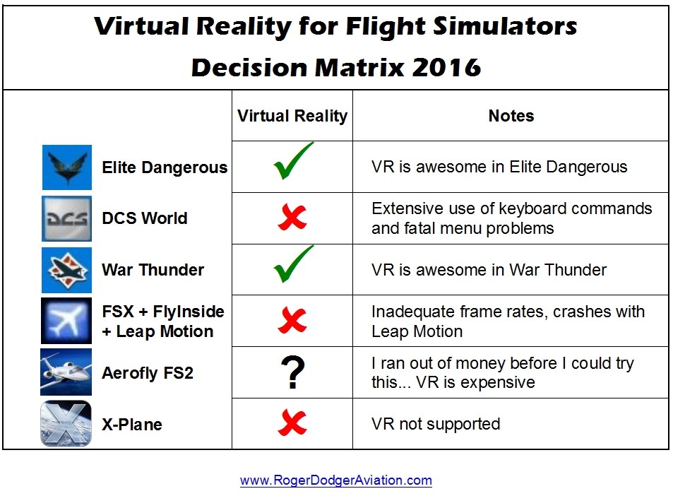
Matrix: Virtual Reality for Flight Simulator
Here is a summary of my findings with the flight sim software. Read on for financial and physical implications.
Virtual Reality for Flight Simulators Decision Matrix 2016
Virtual Reality: Financial Issues
The FlyInside developer recommends FSX Steam because it works better with FlyInside for some reason. I would like to try it, but I’m simply out of money. Virtual Reality costs real money. It is expensive. The Oculus Rift headset was over $600 with shipping, but I also needed a new computer to run it. I shopped smart but still spent over $1160 on a new gaming computer (specs below) and that still wasn’t enough. I’ll need to spend another $600 on a new graphics card before I can run the Rift at high definition 1080p. I bought Leap Motion on sale, but I can’t use it because of the problem with FlyInside FSX. I couldn’t afford to even try Aerofly FS2.
Notice that Virtual Reality did best with games, not simulators. Flight Simulator X was not usable and X-plane doesn’t support VR at all. Think long and hard about spending your money. VR is for gaming, not for simulating.
Virtual Reality: Physical Issues
You can’t wear glasses with the Oculus Rift. Well, technically you can, there is an awkward way to do it, but the headset will push the glasses against your face, which is very uncomfortable. Realistically, it’s contact lenses or nothing and that’s just the way it is right now. Maybe there will be helpful remedies in the future.
Motion sickness is a risk if you’re prone to motion sickness in general. If you typically feel nauseous in a plane or boat or car, you may feel the same in VR. Furthermore, if your computer can’t render VR in 60 frames per second (at least), you may feel nauseous in Virtual Reality for flight simulator. Luckily, motion sickness if easily remedied because you can just take a break and remove the headset for a while.
Pounding heart, sweaty armpits, residual headset heat, dry eyes. Clinical flight simulator research shows that pilots start to have involuntary physical responses to professional flight simulators when the images are rendered higher than 60 fps. In other words, their palms sweat. In my experience, my heart was pounding, I was breathing heavy, and my whole body sweat during combat in War Thunder. I took breaks between sorties to calm down, it was that intense. Sometimes my eyes would get dry in VR because I probably don’t blink as much as I should. Lastly, the Oculus Rift headset gets warm during use, so I needed a fan blowing on me to help me stay comfortable. That’s unusual for me, I typically have a lower than average body temperature.
Virtual Reality: Emotional Responses
I didn’t expect to have any emotional reactions to VR but I did. Virtual Reality for flight simulator wasn’t the only thing I tried, I also looked at some 360 degree videos. When you view these videos, it’s like you are inside the video and you can turn any direction to see what’s happening around you. Several little clips are included in the Oculus library.
One clip showed a young couple on a gondola ride in Venice. The camera was in the boat with them so it seemed like I was riding along with them too. It was a vacation I can’t afford in a city I’ll probably never visit and yet, I was there… virtually.
Another 360 video clip showed a family in Asia somewhere and their house was basically a little shack on stilts in the water and again, I was there… virtually. I was reminded of how lucky I am to even experience VR because my computer and VR headset probably cost more than their annual income.
Is a Virtual Reality headset worth the money if you are a flight simulator enthusiast? It depends on the type of simulating you do. In this article I’ll tell you about my first month with the Oculus Rift headset and Virtual Reality for Flight Simulators. I’ll discuss the four different flight sim platforms I tried with VR and also the physical and financial impacts of these experiments.
The first thing you should know is this: Virtual Reality is a game changer. Accent on the word “game.” I’ll go into more detail in a moment.
The second thing you should know: Virtual Reality costs real money, plenty of it.
Upgrade the Gear
I started my maiden voyage into the world of Virtual Reality for flight simulators a few months ago when I ordered an Oculus Rift. They were on backorder at the time, but even so, I received mine a full month before I expected to. VR headsets need substantial processing power to work effectively, so I bought a new computer at Best Buy and the specs are at the end of this article. I also bought a Leap Motion sensor while it was on sale so I could experiment with FlyInside FSX. If none of that means anything to you, don’t worry, I’ll come back to that in a minute.
Upgrade the Controls
I also upgraded an F311 Side-joystick HOTASby making the control platforms wider to better align the controls with the armrests of my chair. Furthermore, I added a trackball mouse and a drink holder (don’t fly thirsty). I also raised the reinforcement bar so I could use my favorite rudder pedals and attached all fittings with self drilling screws. I used this F311 frame with great success, I can’t VR without it.
For these experiments, I said goodbye to my trusty Saitek switch panels and keyboard mods… you can’t see them while wearing a VR headset. Now, come with me as we explore Virtual Reality for flight simulators…
Elite Dangerous virtual cockpit
Elite Dangerous
My first flight in VR was in space and it was breathtaking but just a bit disappointing. Everything worked correctly, but I found that my graphics card could not power the Oculus Rift at 1080p, so I’m temporarily stuck at 768 until I can afford a more powerful graphics card. Even so… I said the experience is breathtaking and it is. You have stereoscopic vision in VR, just like you have in real life. Your left eye and your right eye see slightly offset views of each object, so this is what makes close objects look close and far objects look far away. In Elite Dangerous, this means I could for the first time, sense the size of the spaceship’s flight deck. I could look down at my arms in the game and see how close they are and then look outside and comprehend the enormity of the space station.
The game isn’t on a screen any more, it’s all around you. You’re inside the game. This is most obvious in combat because you can look up and back and over your shoulder at your enemy. You also should be fully HOTAS so all aircraft functions are assigned to the buttons on your joystick and throttle because it’s too inconvenient to use the keyboard. That means you also have to memorize all your button assignments. One of the great limitations of VR is that you can no longer see real-world buttons and switches. However, you can use Voice Attack to simply speak commands to your spaceship. For example, you can verbally tell it to extend landing gear, and that is perfectly plausible in this futuristic environment.
Conclusion: from now on, I will only play Elite Dangerous in Virtual Reality. That’s how good it is.
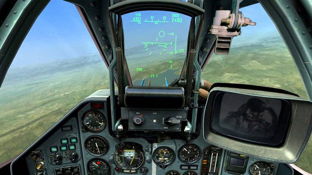
DCS World
I couldn’t wait to try DCS World with the Oculus Rift, but unfortunately it didn’t go as smoothly as Elite Dangerous. First of all, the DCS menus were very difficult to use and in some cases, they just didn’t work at all. It was a time-consuming chore just to set up my Saitek X-52 HOTAS controls and rudder pedals. I flew several tutorial missions, but many of the lesson tasks required the use of keyboard commands, so I had to put my keyboard on my lap. I could kind of see the keyboard in the gap between the bottom of the Rift headset and my cheek, but this is not a reasonable option. Perhaps I could have assigned specific functions to HOTAS buttons, but there are so many of them and, again, navigating the DCS controls menu in VR is a crapshoot at best.
Disclaimer: it’s really difficult to take screen shots in Virtual Reality for flight simulators, so for this article I borrowed representative pics from other sources. This has no impact on the validity of my findings.
I appreciate the realism of DCS World, but lifting the Rift headset repeatedly to look at a paper checklist or the keyboard is a no-go. I applaud the young man in this video for diligently looking at his checklist, but every time he lifts the headset with one hand, the Rift lenses come in contact with his forehead. Be very cautious with the Rift lenses, they are delicate! Repeated exposure to sweat or hair or grease can damage the Oculus Rift lenses.
DCS World looks astonishingly great, even if it’s not fully usable. One of the aircraft I selected was the TF-51 Mustang and I really felt how cramped the cockpit is. I also tried a few landings and found them to be a more realistic experience in VR than my previous experience. Instrumentation was a little hard to read because of the lower resolution required of my graphics card. I would love to try all of this again at 1080p.
Conclusion: I won’t play DCS World again in VR until there is some work around or fix for the menus.
It’s easy to mount the Oculus Rift sensor on a tripod.
The Oculus Rift sensor is designed to sit on a desk or table, but sometimes it is much more convenient to mount the sensor on a tripod. For example, my flight simulator does not have a table sitting in front of but this tripod works nicely. It’s easy to mount the sensor on a tripod, I’ll show you how.
This is an old, spare tripod that I wasn’t using any more. You can see where I repaired the crank many years ago. I’ll use this tripod for my Oculus Rift now.
Quick note: You’ll notice I covered the Rift sensor. I did that because the sensor is quite sensitive to bright light and I’m using some pretty bright lights to film this video. You probably won’t need to worry about covering the sensor like I did.
Instructions
If you currently use the Oculus Rift with the sensor sitting on a desk, take a moment to measure the distance from the floor to the sensor. Unclip the wire and let’s take a look at the base of the stand. The base will not unscrew here… look farther up toward the sensor. This is where it unscrews. That’s actually a lot better for us than unscrewing the base. Remove the quick release plate from the tripod. Screw the sensor onto the plate. The threads should match perfectly. Both the sensor and the plate have standard quarter-twenty threads. Return the quick release plate to the tripod. Adjust the height so the sensor is the same distance from the floor as it was before. If you need to re-calibrate the location of the sensor, you can do that in the Oculus Rift software. I recommend using some small strips of Velcro to attach the wire to the tripod.
Simply position the sensor so it points at your headset and take off ! ! !
My joystick, throttle and rudder pedals are secured in place with a framework of PVC pipes and lumber. It is item F311, the Side Joystick Frame and I can help you build one for yourself.
This modification to the Saitek Pro Flight Yoke uses zip ties and springs that I bought from a home improvement store. It’s a very popular modification that I’ll call the Saitek Pro Flight Yoke Ultimate Fix. The springs will attach to the center shaft and the four screw posts.
NOTE: modifying the Saitek yoke will void the warranty. However, if you purchased the yoke over two years ago, the warranty has already expired.
Credit for this idea should go to Tom Gromko who published this method on the AVSIM forum.
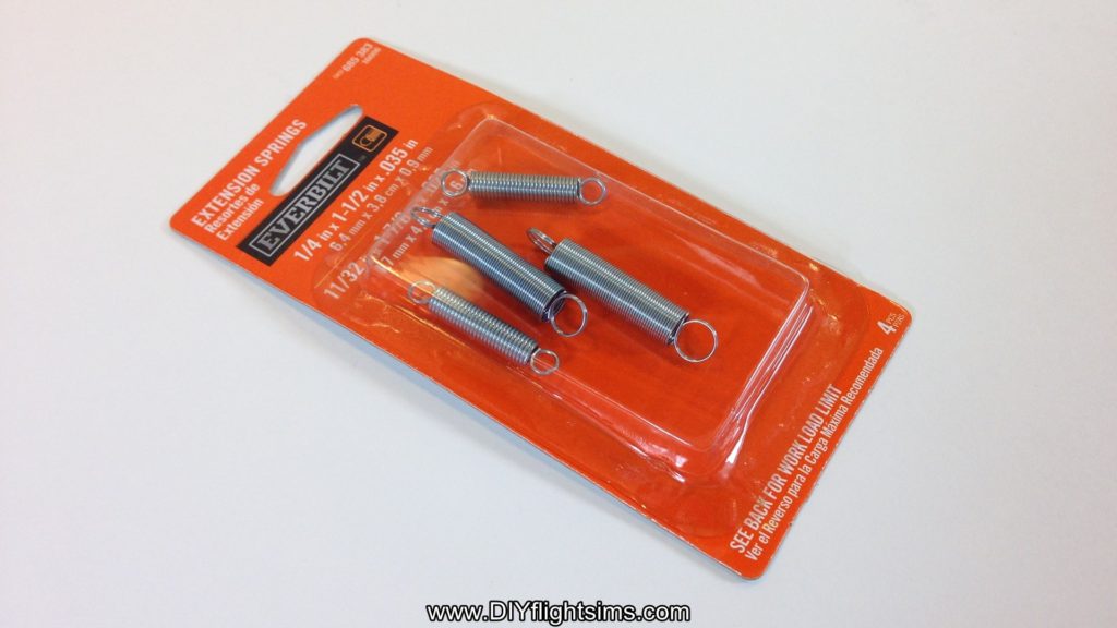
Springs for the Saitek Yoke
Before we start, I’m assuming you’ve already removed the pitch spring and swing arms as shown in the disassembly video. You can leave the roll return spring in place for this mod, or if you want less resistance, you can remove it. You’ll notice that I’ve removed it for this video.
The springs we are using are from Home Depot and it costs less than $4.00 USD. This package comes with four springs, but we will only use the larger two. If you can’t find these springs exactly, find ones with a similar load limit – about 2.4 pounds.
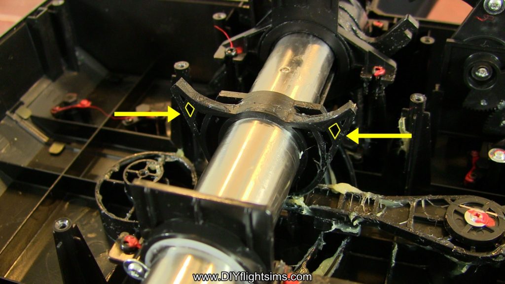
Let’s get started. Rotate the yoke so the back of the control housing is facing you and it’s best to prop up the yoke on some boards or something. Locate these horns on the center shaft and specifically locate this small gap in the plastic structure. Use a drill and a 1/8” drill bit to make a hole right through that small gap and then repeat on the other side.
A 1/8” hole should be large enough for these mini Zip Ties to fit through them. The springs will loop over the screw posts on the left side and the right side and then attach to the center shaft. Unfortunately, the springs tend to slide off of the screw posts while we’re working with them, so use a small file to create a groove in the plastic. This file is actually three-sided, therefore it’s really handy for this job. This groove we’re making faces the back of the yoke. For this screw post, file a groove on the front side, towards the yoke handle. The spring stretches easily between the posts and it fits nicely in the groove.
When you work on this post, be very careful not to damage the circuit board or any wiring here so it’s ok to take your time with this step.
Install Replacement Springs
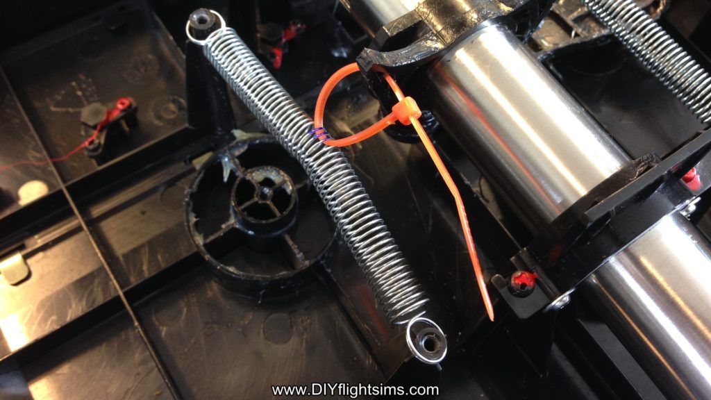
Now we want to attach the horn on the center shaft to the exact center of the springs. I used calipers to determine the middle point of the spring. You don’t have to use calipers, you can measure carefully or you can even count the strands on the spring to determine the middle. Mark the middle three strands with a sharpie and then remove the spring. The spring can be a little hard to hold on to, consequently, use a zip tie to hold the ends while you fold it over like this.
Look for the mark you made and use a small screwdriver to loop under those three strands on the spring. Then, loop a zip tie under those same three strands and remove the screwdriver. This green zip tie was just temporary and we’re going to cut it off now.
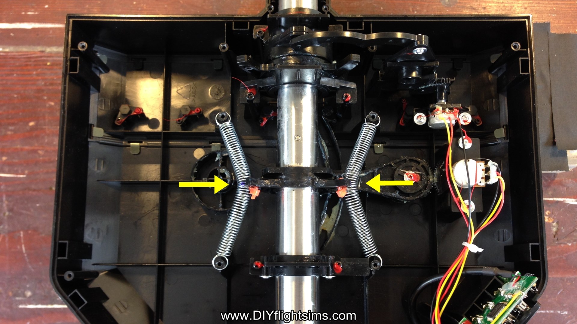
Stretch the spring between the two screw posts again and loop the zip tie through the hole you drilled in the horn and then attach the zip tie like this. Repeat this process on the other side. Now tighten both zip ties all the way and clip off the excess from the zip ties.
Finishing Steps for the Saitek Pro Flight Yoke Ultimate Fix
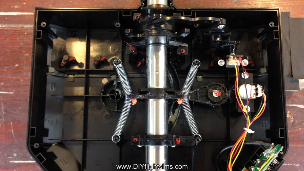
Finally, replace the lid and try it out.
Hold down the yoke housing with one hand. Note how easy it is to make small pitch changes when you don’t have to struggle against that center detent. You may notice some noise coming from the springs if you are making large control inputs. But if you’re otherwise happy with the results, reattach the control housing. There are 14 screws.
I’ve developed several ways to modify the Saitek Pro Flight Yoke, but first we need to open it up without damaging it or losing parts. Prepare to see inside the Saitek Pro Flight Yoke!
Saitek Yoke Disassembly
This is the very popular Saitek Pro Flight Yoke. This video will demonstrate how to take apart the control housing. You will also see how to remove parts of the pitch and roll mechanisms. We will then be able to modify and improve the pitch and roll movements in later videos.
Note: Disassembly of the Saitek yoke will void the manufacturer’s warranty. However, if you bought the yoke over two years ago, the warranty has already expired.
Let’s get started. Disconnect the yoke from your computer and then turn it upside down on a table. There are 12 screws that hold on the bottom of the control housing. Carefully loosen all of these screws. There are also 2 tiny screws at the base of the control shaft. Remove these and be careful not to lose them. Remove the bottom of the control housing. Most of the screws will probably remain in the housing, and that’s fine. That will save you the trouble of replacing them later.
See Inside the Saitek Pro Flight Yoke
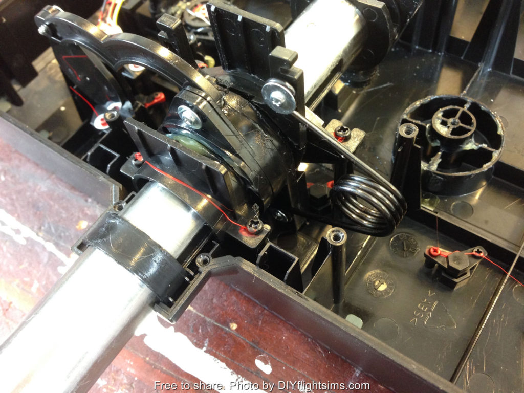
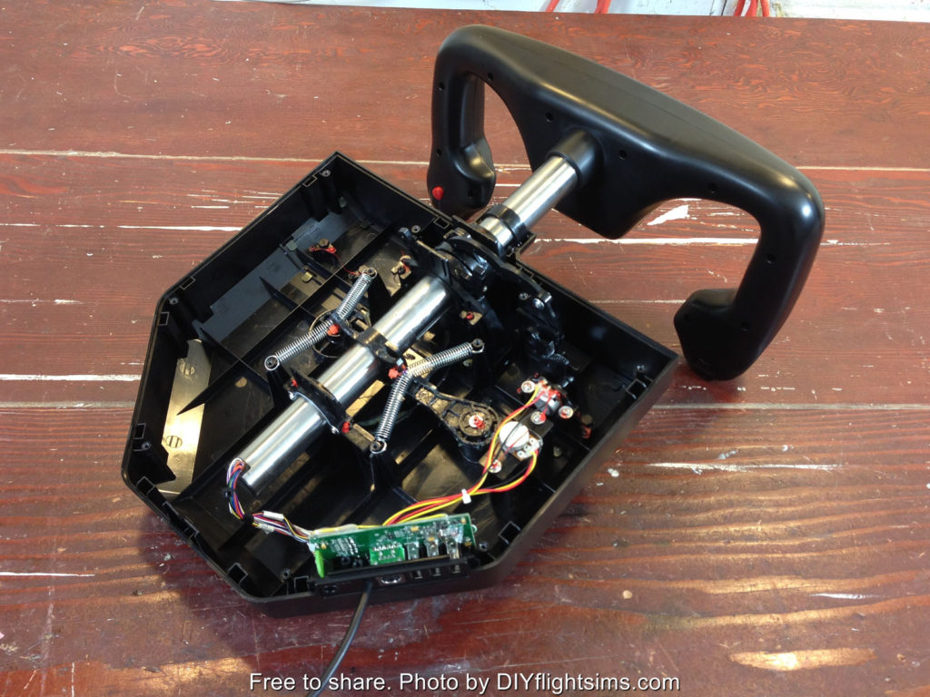
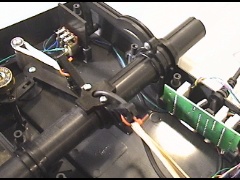
Let’s look at the major components of the yoke. Here is the spring that returns the yoke to its center pitch position. This spring and associated mechanism is what makes the yoke feel like it has a detent. It makes fine pitch adjustments difficult. Even if you’re trying to make small, precise pitch adjustments, you still have to overcome the full tension of this spring. We’re going to get rid of it. Let’s look at some of the other components. This is the pitch potentiometer over here and the potentiometer for the roll movement is here. Here’s another view of the roll movement. This is the roll return spring. This spring is not as objectionable as the pitch return spring, but we will show you how to remove it anyway.
Pitch Axis
Let’s get to work on that nasty pitch return spring. Remove the screw from one side of the spring. The spring is under tension, so carefully unhook it from the post and remove the other screw. Now we see there is actually a second spring underneath the first one! The pitch spring is connected to two swing arms and the swing arms come together at this elbow. Remove this pivot screw (this is where your hands get greasy). Reach in and hold the control arm steady with your left hand and then use your right hand to pull up on the elbow to remove it from its seat. The swing arms are held in tension by the spring, so you’ll need to unhook them from the spring also. Remove both swing arms and then you will see that nasty spring. Verify the control arm is still attached and is still moving the pitch potentiometer. The yoke now moves freely forward and back with no centering feature at all as a result, it is prepared for whatever modification you would like to make.
Roll Axis
The roll movement on the Saitek yoke is not nearly as problematic as the pitch. However, if you still wish to modify it, here is how you remove the return spring. The return spring is held in place with only two screws. The top screw is easy to reach with a small screwdriver. The spring is under tension so carefully unhook it from the mounting post. Turn the yoke all the way to the left. The bottom screw is here, but it’s hard to reach. It’s not a straight shot, but you can still reach it with a small screwdriver so carefully loosen the bottom screw. Be careful not to round out the head of the screw. Remove the screw and the spring from the control housing. Now there are no centering mechanisms for either the roll axis or the pitch axis.
Reassembly
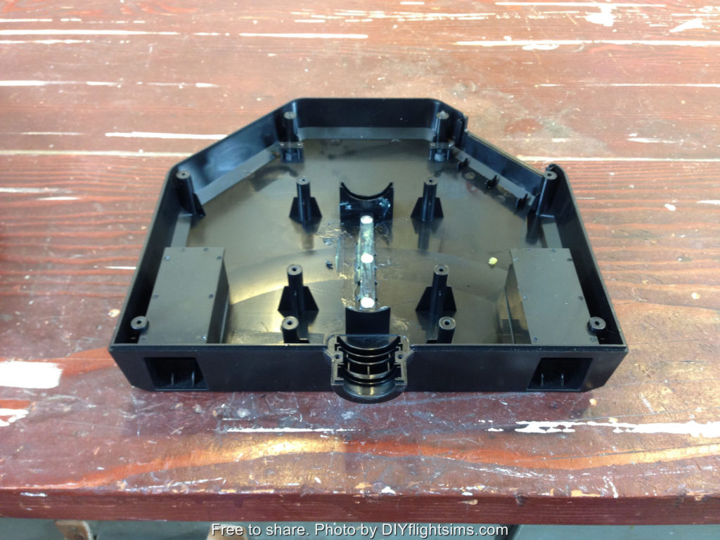
After you’ve completed your modification, you will need to reattach the bottom of the control housing. There are three tabs that must fit into three slots on the bottom of the housing. If you don’t have all three tabs aligned with the slots, the housing won’t fit. Sometimes it takes some wiggling to get the housing to fit correctly. There is also a tab at the back of the housing that must fit inside the lip. Now you know how to take apart the Saitek yoke and how to put it back together again. The remaining videos in this series will show several ways to modify and improve the yoke.
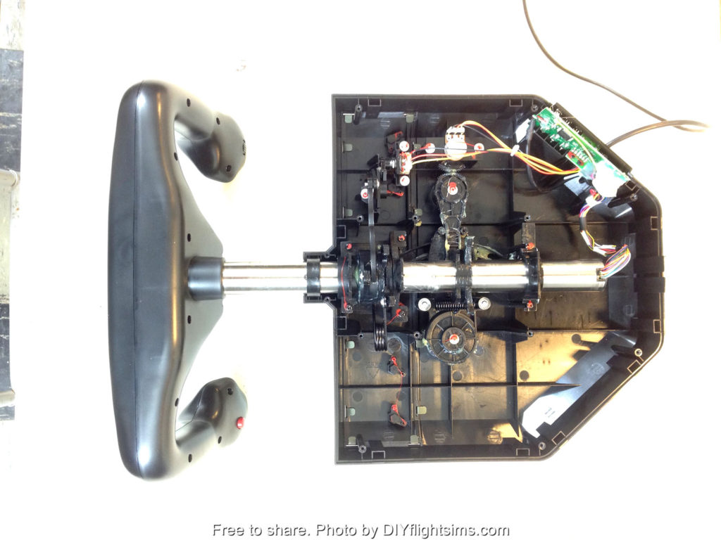
Below are some high-resolution photos of the major components inside the Saitek Pro Flight Yoke….
How to disassemble the Saitek Pro Flight Yoke
Pitch potentiometer
Major interior components of the Saitek Pro Flight Yoke
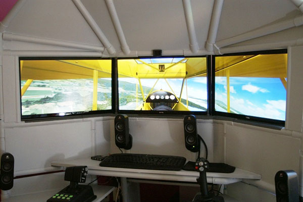
DIY triple screen flight simulator with HOTAS by Ola
Great to see this innovative build from Ola! He made several modifications to the DIY Triple Screen Flight Simulator project to better match the type of flying he enjoys. You can see from the screen shot he is flying a Piper Cub over the summer countryside. He is also running Flight Simulator X. The stock project from DIY Flight Sims calls for a yoke and throttle quadrant, but Ola designed two podiums on either side that support HOTAS (Hands On Throttle and Stick) flight controls. I fully support modifying the designs to match your needs. It’s exciting to see all the variations that builders can create. I never predicted I would see a Triple Screen Flight Simulator with HOTAS.
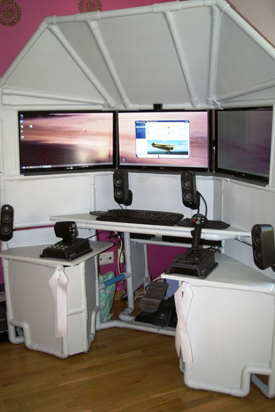
Logitech G940
Ola is using the Logitech G940 HOTAS flight system with his home flight sim cockpit. I’ve always wanted to try out this system but I haven’t had the opportunity yet. I’ve owned lots of Logitech products and I’ve always been pleased with their reliability and affordability. For some reason, I’m not finding this available on Amazon or Newegg. Amazon actually does have it listed at $620 USD, which is way too expensive, but could be an indication this product is discontinued. I hope it’s not discontinued, but it is a force-feedback joystick, and it’s hard for those to sell successfully in the already competitive joystick market.
Especially relevant are the 2″ Velcro strips on either side of the triple screen flight simulator with HOTAS. You might not know this unless you’ve experienced it, but if you use rudder pedals while sitting in an office chair, you immediately find that pushing on the pedals, results in you rolling away in the chair. The remedy is to strap the chair in place with sturdy Velcro strips. Most of all, you literally get to “strap in” when preparing to fly your simulator.
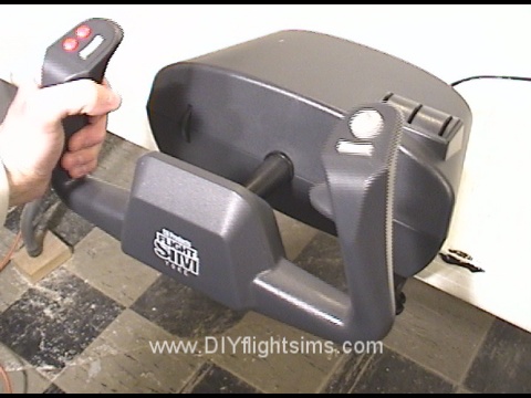
This is the CH Products Flight Sim Yoke. I’m going to disassemble it to show all the hackers and makers what to expect if they ever want to modify one.
Note: This will void the manufacturer’s warranty, but if you bought the yoke over a year ago the warranty has already expired.
Start by popping off the knob handles from the little mini-levers. Unscrew the table clamps, so now you have access to this corner screw. The screws in the opposite corners are under the rubber stoppers. Also there’s a screw under the warranty sticker of course. There are 8 screws total.
Now we’ve re-attached the table clamps and removed the top in order to show the inner workings of the control housing. Be careful that the back of the shaft doesn’t pop up. There’s a lever underneath the shaft, and this links to the pitch potentiometer. Note you will need to verify it’s seated correctly when you re-assemble the housing later. Here’s the linkage for the pitch potentiometer. Note that the pitch trim wheel moves the potentiometer too. The trim is way too sensitive to be useful, as a result, I just forget about it and use the Saitek trim wheel (which is great).
Additional Observations
The roll movement is linked to the other potentiometer at the back of the unit. If you have a separate throttle quadrant (and I hope you do), these mini-levers on the top of the housing become redundant. You can remove these 6 screws and the wiring clip to take out this component. The yoke grip can be disassembled if you’re adding buttons, or something similar. There are 10 screws total in the grip.
Once the face is off, you can see all the wires from the various buttons. The wires snake through the shaft and come out here. The centering springs return the yoke to its middle position for pitch and roll. Most noteworthy, these springs, plus the friction of the control shaft can make it difficult to make subtle control movements like during a landing flare. Click to this blog post and video to see how to fix the CH Products Yoke to avoid over-controlling your home flight simulator.
The CH Products Flight Sim Yoke is a solid addition to your home flight simulator. Even so, we can modify it a little to make the yoke work more smoothly because the spring tension and the friction within the mechanism can cause you to over-control the airplane. Sometimes you need to make more subtle control inputs.Ideally, when you have the airplane trimmed properly, you can fly with a light touch on the yoke. For example, if you’re over-controlling the airplane during landing, you’ll porpoise down the runway. Well if you don’t do that in real life, it’s embarrassing when it happens in flight simulator.
Our previous video showed how to disassemble the yoke. This video will show the CH Products yoke modification. I’m basically replacing the tension springs with rubber bands. The mod is reversible, so if you decide you don’t like it, you can change it back to the way it was before.
CH Products Yoke Modification
Note: disassembling consumer products may void the manufacturer’s warranty.
We will start by removing the springs. There is continuous tension on the spring, so push it down onto the pylon. Then remove the screw and washer… and carefully unhook the spring. Reattach the screw. Unhook the other end of the spring from the shaft. Repeat on the other side to remove the second spring. This cable is held in place with a small zip tie. Carefully snip it off. We’re going to use the hole that the zip tie was in…but we’re going to need one on the other side too. Here’s the existing hole, and now we’re drilling one in the same place on the other side. This is a one eighth inch drill bit. Just removing the little plastic shavings here.
Now we have our own little zip ties for the next step, and rubber bands. Insert the zip tie through the hole. Take two rubber bands and loop them over themselves like this. Connect the zip tie to one end of the rubber bands like this. Then stretch the rubber band over the pylon. Repeat on the other side. Notice I’m holding the yoke handle when I loop the rubber bands over the pylon.
Everything is looking good so far so let’s tighten up the zip ties. Loosen the rubber bands, cinch up the zip tie, then loop the rubber bands over the pylon again. Here’s the opposite side. Try not to get the rubber bands twisted too much. Snip off the ends of the zip ties.
Finishing Steps
Now you might ask, isn’t there a simpler way? If you look at how the shaft is constructed, you’ll notice we can simply loop these rubber bands on the opposite horn like this and loop the other rubber bands on the other side. Well that does work, but not very well. The rubber bands tend to rub against each another and make a banjo sound. I’m assuming you don’t want your yoke to sound like a banjo, so that’s out.
Remember this lever needs to be seated correctly on the bottom of the shaft, and the sleeves need to set in the grooves on the back of the unit. Finally, this wiring harness was disconnected from the mini-levers that we removed in the previous video. We don’t want it flopping around, so we attached it to these other wires with a zip tie, and everything is tucked away nicely.
The CH Products yoke modification is complete! Now the yoke has a better response to those subtle little control inputs that we tend to use when the airplane is trimmed for cruise flight, or any time a soft touch is necessary.
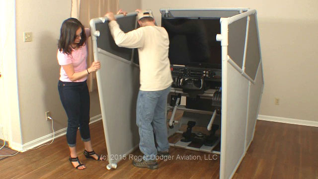
DIY Flight Sim Pod Final Assembly Video Transcript
This is an excerpt from the DIY Flight Sim Pod instructional video. The video and associated manual show you every step in building this home flight simulator project.
In this final section, we’re going to populate the Inner Frame with computer hardware. Furthermore, we will assemble all the pieces of the Flight Sim Pod. Your new flight simulator will soon be finished!
We see here the Inner Frame, all painted and masking tape removed, lt’s look at the right side of the frame. Here on the Computer Shelf we can set a desktop computer, and a powerstrip on the Top Shelf.
Next: the monitor or HDTV. It is a very good idea to get help from a friend while mounting the HDTV. You can’t actually see the bracket when you clip onto it, so it helps to have a second pair of eyes watching. Make sure it’s centered in the frame also.
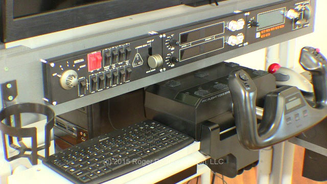
Install the switch panels and then add the yoke, and beside the yoke, the throttle quadrant. I have attached Velcro to the top of the throttle quadrant for the trackball mouse. There is enough room on the yoke housing for a mini-keyboard, or it can go beside the yoke. Don’t forget a drink holder!
Attach the rudder pedals, and add the speakers. Remember the Chair Staytheres? I painted these also. They have Velcro that loops over this horizontal bar. Notice when you use the Chair Staythere you have to reach way down to get it and you might want an easier way. I simply measured 7” from the end of the pipe and drilled two holes and then I tied on a piece of boot string and hung it from the pipe above. I did this on both sides.
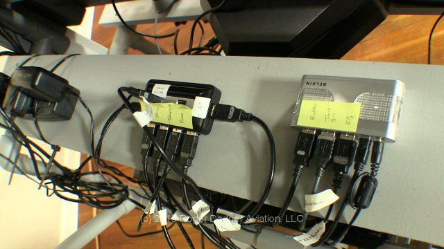
Now I don’t have to reach down so far. With all the peripheral equipment on this machine, we end up with a lot of wires. I loop the wires and use strips of Velcro to keep them organized. If I need a USB extension, I use Velcro straps to help keep it secure. Use it for the rudder pedals so the wire won’t get tangled up with your feet. I secured the USB hubs with Velcro too. I recommend labeling the USB wires, there are so many of them
Once everything is hooked up, it’s time for a test drive! Make sure all the peripherals work correctly.
We’re almost finished with the DIY Flight Sim Pod Final Assembly. For the final step, I really recommend you get help from a friend because you’ll need someone to hold the Side Wall in place while you attach it to the three interface points. The first point is near the Side Boards. There are two points in the front that slide into place also
Secure each interface point with a self-drilling screw. That Side Wall will stand by itself so you can attach the other Side Wall. Attach all three interface points with self-drilling screws. Next replace this bottom support pipe, or the tail end extension, your choice. Secure with self-drilling screws.
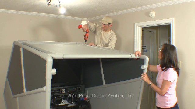
Carry in the Top Canopy, and set the 1×4 board on the ledge near the top of the support pillars. Have your partner hold the back of the Top Canopy while you attach the front. Once the front two corners are in, you can attach one of the back corners. Secure the front two corners with self-drilling screws.
Now we can attach the top support pipe. First insert it in the left side. Remember, we left the right side of the Top Canopy loose for this reason. Attach both pipes simultaneously. Attach four self-drilling screws: The two back corners of the Top Canopy, and both sides of the top support pipe.


Recent Comments